Amplifier Crossover Distortion

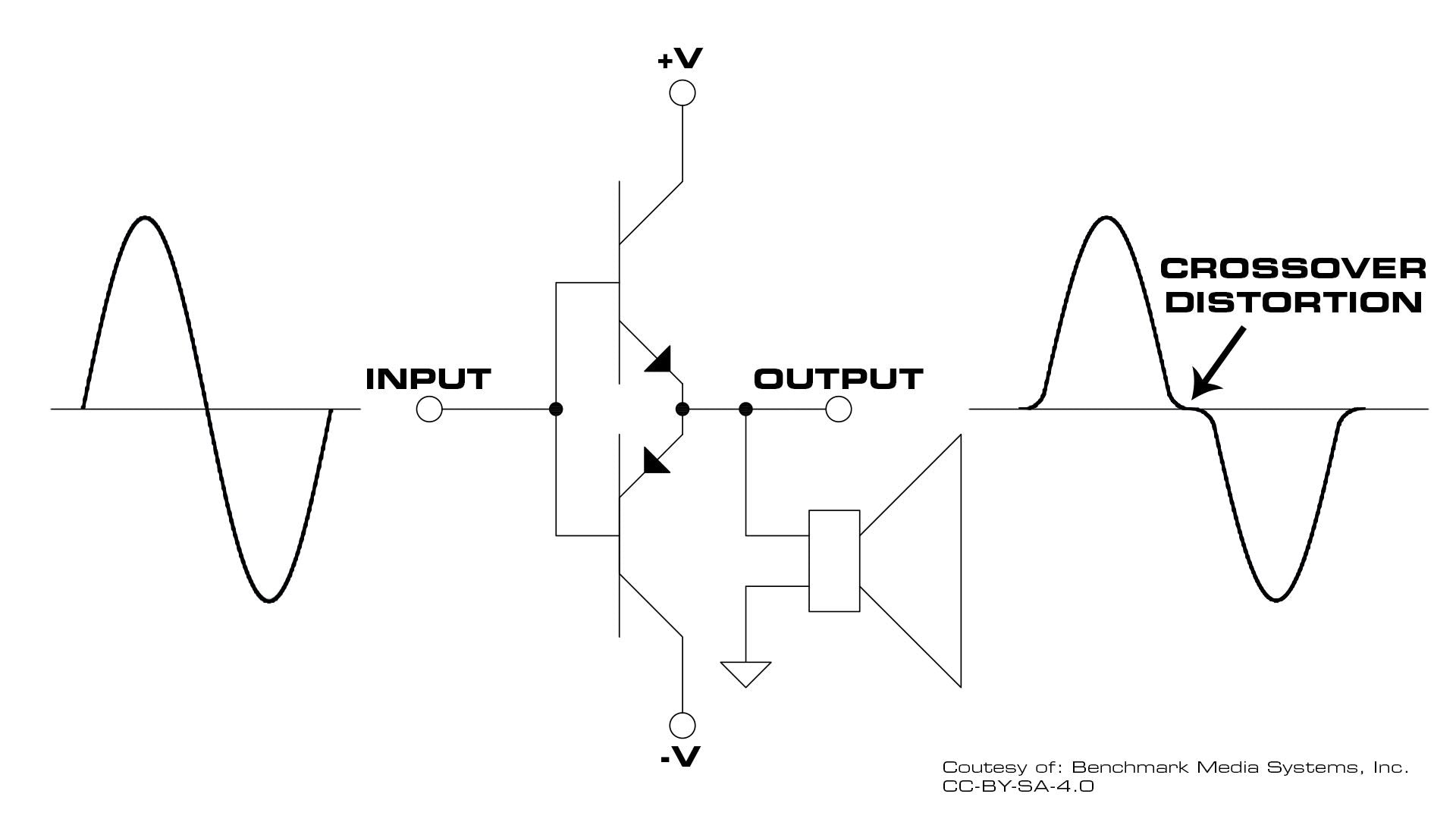
Most audio power amplifiers suffer from a defect known as "crossover distortion". This distortion is particularly troublesome at low output levels. At low power levels, the crossover distortion can rise to a high percentage of the output level and become the dominant source of distortion.
The Important First Watt
Dick Olsher once said that "the first Watt is the most important Watt". We agree!
At normal listening levels, in a studio control room or home environment, an amplifier spends much of its time delivering about 1 Watt of power. Musical peaks may demand 50 to 100 Watts, but most of the musical content is reproduced using a few Watts. For this reason, 1st-watt performance is crucial to the overall sound of the amplifier.
Amplifier THD+N is often only specified at high output levels. It is relatively rare to see specifications for the performance at 1 Watt. An amplifier that is relatively clean at high output levels may deliver poor performance in the 1st Watt, but this will not be reflected in the published (high output level) specifications. Look for both low and high-level specifications when selecting a power amplifier.
Push-Pull
Crossover distortion occurs every time an amplifier output device turns on or off. In most amplifiers, these transitions occur every time the output current reverses. One output device is dedicated to pushing the speaker cone outward, while the other is dedicated to pulling the speaker cone inward. We call this combination of output devices a push-pull output stage. Larger amplifiers use multiple push and pull output devices running in parallel, but the operating principle is the same.
When an amplifier attempts to damp the motion of a speaker, the speaker may cause a series of current reversals that increase the occurrence of crossover distortion events.
The "Sound" of Crossover Distortion
Crossover distortion is particularly insidious in that it is not usually harmonic. The timing of the 0-current crossover events is a function of all of the frequencies being reproduced by the amplifier. This interaction causes intermodulation distortion (IMD) which is much more audible than harmonic distortion (THD). The distortion tones produced by IMD do not occur where our ears expect to hear distortion. IMD can cause two musical instruments to interact in a way that produces distortion tones that are never naturally produced by either instrument. For this reason, IMD sounds unnatural and unmusical to our ears.
The "Sound" of Harmonic Distortion
In contrast, harmonic distortion tends to be less noticeable than IMD because it resembles the distortion produced by musical instruments. Each musical instrument produces a rich spectrum of harmonic distortion in a unique pattern that distinguishes it from all other types of instruments. A flute and a violin may play the same note but they sound very different because they produce very different patterns of harmonic distortion. Variations in harmonic distortion give musical instruments their unique voice.
If an amplifier adds some harmonic distortion, this may be small relative to the harmonics produced by the musical instruments, and the amplifier's distortion may go unnoticed. If the harmonic distortion produced by the amplifier is high enough, it may cause a noticeable change in the sound of some instruments. Some listeners enjoy the "warmth" or "color" added by an amplifier's harmonic distortion. In extreme cases, harmonic distortion can make instruments difficult to identify.
Crossover Distortion is Not Entirely Harmonic
Crossover distortion has a strong IMD component and this makes it much more audible and objectionable than harmonic distortion. For this reason, amplifiers use a number of topologies and techniques to minimize the crossover distortion produced by push-pull output stages.
Where Do We Find Push-Pull Output Stages?
There are many types (or "classes") of linear amplifiers that use push-pull output stages. These include:
- All class-B amplifiers
- All class-AB amplifiers
- Some class-A amplifiers
- All class-H and class-G amplifiers
Most class-D (switching amplifiers) also use push-pull output devices. The push-pull devices in these switching amplifiers make abrupt transitions between full-on and full-off states. These switching transients occur at a high repetition rate and generally contribute to an overall increase in distortion and noise.
Class-B Amplifiers
High Crossover Distortion, Good Efficiency
In a class-B amplifier, only one output device is on at a time. To make matters worse, there is usually a dead-zone where neither device is turned on. This dead-zone is crossed whenever the current to the speaker reverses. Every crossing causes a significant ripple in the output waveform. Class-B amplifiers perform very poorly at low output levels, but waste no power when idle.
Class-AB Amplifiers
Low Crossover Distortion, Average Efficiency
Class-AB amplifiers attempt to reduce crossover distortion by overlapping the operating regions of the push and pull output devices. This overlap (or bias) allows a gradual transition between the push and pull devices and this greatly reduces the crossover distortion. But this overlap means that the push and pull devices are lightly pulling against each other when the amplifier is idle. This overlap increases the idle power consumption of the amplifier and the amount of overlap must be carefully controlled. Too much overlap will cause overheating. Too little overlap will cause a rise in crossover distortion. The distortion performance of a class-AB amplifier is largely a function of how well this overlap is executed. Temperature, loading, and aging can take a class-AB amplifier out of this sweet spot: If the overlap is lost, the class-AB amplifier operates as a class-B amplifier. If the overlap gets too large, the class-AB amplifier spends more time in a low-efficiency class-A mode.
Class-A
No Crossover Distortion, Low Efficiency
Class-A amplifiers do not produce crossover distortion. The output device or output devices do not transition between on and off states. All output devices are always on in a class-A amplifier. This configuration wastes massive amounts of power, but it prevents crossover distortion. Class-A amplifiers are known for producing very little distortion at low levels.
Some low-power class-A amplifiers are single-ended. These amplifiers use an active device to push the output in one direction while the load pulls it back in the other direction. Single-ended class-A amplifiers tend to create substantial even-order harmonics, especially at higher output levels. These even-order harmonics are much more pleasing to the ear than the IMD distortion produced by crossover distortion, but they can add a substantial coloration to the music.
Push-pull class-A amplifiers attempt to reduce the even-order harmonics without causing crossover distortion. These class-A amplifiers tend to be much more transparent than single-ended class-A amplifiers.
Class-H and Class-G
Some Crossover Distortion, High Efficiency
Class-H and class-G amplifiers are class-AB amplifiers with additional push-pull output devices that activate when large voltage peaks are encountered. When these extra devices turn on or off, they create additional crossover distortion transients. A class-AB has one crossover region near 0 output current, but class H or G amplifiers have 3 or 5 crossover regions. These additional crossover regions increase the crossover distortion problems by a factor of 3 or 5 relative to a class-AB amplifier. The advantage of switching between low-level and high-level output devices is that the efficiency can be greatly improved relative to a traditional class-AB amplifier. Class H or G amplifiers offer a good alternative to class-D amplifiers when high efficiency is required.
Feedback Error Correction
Most amplifiers use a substantial amount of feedback to reduce the distortion at the output of the amplifier. A feedback circuit compares the amplifier output to the input signal and produces a difference signal that is added to the input. This feedback corrects distortion after it starts to occur. If a distortion event happens quickly, the feedback network may be too slow to correct the distortion.
Crossover distortion can create fast transients that are too short to be corrected by a feedback network. The feedback network can actually extend the period of time over which the error occurs. Most class-AB amplifiers will show crossover distortion artifacts that have been stretched in time by ringing in the feedback network. This ringing occurs because the feedback network must settle after encountering the transient caused by the crossover event. Feedback networks correct distortion after it starts to occur.
Feedforward Error Correction
Benchmark's AHB2 power amplifier has a unique patented feedforward error correction system that virtually eliminates all traces of crossover distortion. Like a feedback system, the amplifier output is compared to the input and a difference signal is created. But, instead of feeding this signal back to the input, it is added to the output to cancel the crossover distortion. The distortion is corrected before it reaches the final output of the amplifier. There is no ringing and no settling time because we do not need to wait for a feedback loop to respond. The correction happens in perfect synchronization with the error, and the entire error is removed.
Feedforward with Feedback
A deeper look into the AHB2 will reveal a sophisticated combination of feedback and feedforward systems. It is important to note that it is the feedforward system that handles the difficult task of removing the fast transients produced by crossover distortion. The feedforward system eliminates crossover distortion before the feedback is applied. For this reason, the feedback systems are fully isolated from the crossover transients.
Clean as Class-A with the Efficiency of Class-D
The AHB2 is cleaner than the best class-A amplifier and it is almost as efficient as a class-D switching amplifier. The feedforward system is so effective at eliminating crossover distortion that we were able to leverage some of the efficiency features of class-B and class-H amplifiers. To achieve this, we reduced the bias current in the class-AB output stage to achieve a standby power consumption that approaches that of class-B amplifiers. We also leveraged the efficiency provided by class-H tracking rails. Without the feedforward error correction, these efficiency enhancements would have produced higher crossover distortion. The feedforward system removes all traces of the crossover distortion that would have been produced by these enhancements.
Sometimes it is possible to have the best of two worlds.
Also in Audio Application Notes
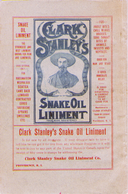

Audiophile Snake Oil
The Audiophile Wild West
Audiophiles live in the wild west. $495 will buy an "audiophile fuse" to replace the $1 generic fuse that came in your audio amplifier. $10,000 will buy a set of "audiophile speaker cables" to replace the $20 wires you purchased at the local hardware store. We are told that these $10,000 cables can be improved if we add a set of $300 "cable elevators" to dampen vibrations. You didn't even know that you needed elevators! And let's not forget to budget at least $200 for each of the "isolation platforms" we will need under our electronic components. Furthermore, it seems that any so-called "audiophile power cord" that costs less than $100, does not belong in a high-end system. And, if cost is no object, there are premium versions of each that can be purchased by the most discerning customers. A top-of-the line power cord could run $5000. One magazine claims that "the majority of listeners were able to hear the difference between a $5 power cable and a $5,000 power cord". Can you hear the difference? If not, are you really an audiophile?

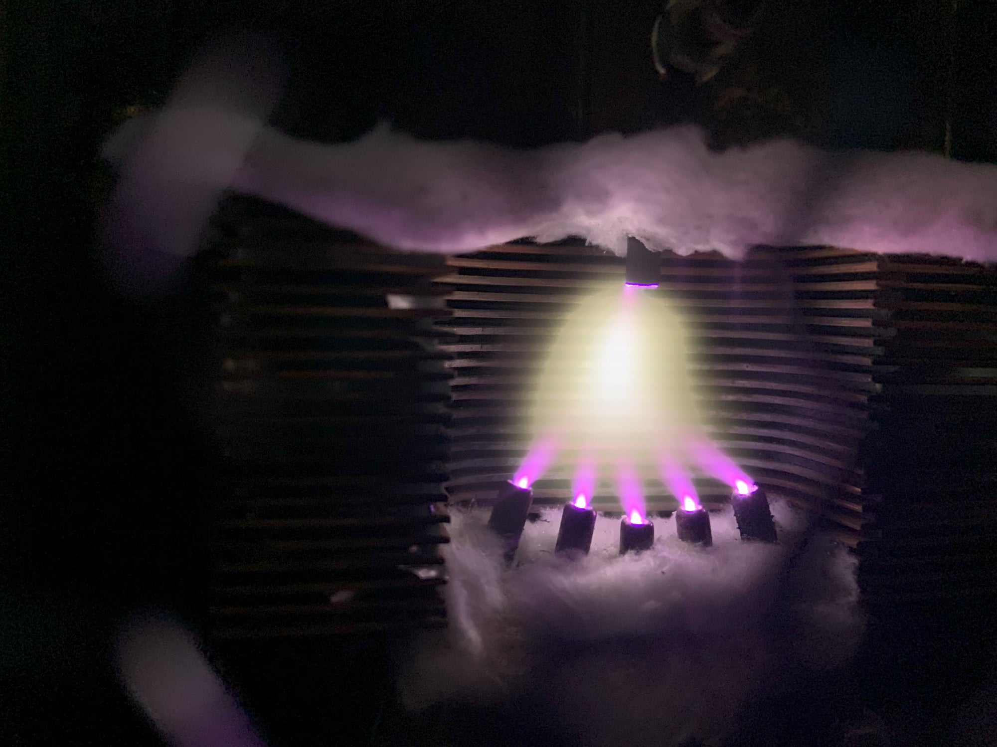
Making Sound with Plasma - Hill Plasmatronics Tweeter
At the 2023 AXPONA show in Chicago, I had the opportunity to see and hear the Hill Plasmatronics tweeter. I also had the great pleasure of meeting Dr. Alan Hill, the physicist who invented this unique device.
The plasma driver has no moving parts and no diaphragm. Sound is emitted directly from the thermal expansion and contraction of an electrically sustained plasma. The plasma is generated within a stream of helium gas. In the demonstration, there was a large helium tank on the floor with a sufficient supply for several hours of listening.

While a tank of helium, tubing, high voltage power supplies, and the smell of smoke may not be appropriate for every living room, this was absolutely the best thing I experienced at the show!
- John Siau

Audio Calculators
We have added an "Audio Calculators" section to our webpage. Click "Calculators" on the top menu to see more like these: