Asynchronous Upsampling to 110 kHz

Overview
Benchmark DAC1 converters use upsampling techniques to improve the quality of the digital to analog conversion. Benchmark’s choice of 110 kHz is slightly unorthodox. It may seem more logical to upsample by 2X or 4X and convert at standard sample rates such as 88.2 kHz, 96 kHz, 176.4 kHz or even 192 kHz. Intuition may suggest that integer ratios would produce the best results. Intuition may also suggest that higher is better, and therefore 192 kHz would be the “best” choice for an output sample rate. Unfortunately, intuition often leads us down the wrong path if it is not balanced with reason and scientific analysis. Benchmark’s analysis and testing has shown that 110 kHz offers advantages over the choices that seem more reasonable. The following is a short summary of the decisions that led to our choice of the 110 kHz sampling rate:
Asynchronous Upsampling Solved the Jitter Problem
Early in the design process, we identified a distinct performance advantage that could only be achieved using asynchronous upsampling. The digital signals feeding any outboard D/A converter contain too much jitter to directly drive the D/A sampling circuits. However, the conversion clock can be entirely independent from the data transport clock if upsampling is asynchronous. The performance of an upsampling circuit is limited only by the precision of the digital signal processing (DSP) allocated to the process. Our intuition may suggest that synchronous conversion is superior to asynchronous, but this is not the case. Our tests showed that asynchronous upsampling could achieve the same performance as synchronous upsampling, but with the distinct advantage of jitter attenuation. On the basis of jitter attenuation, we chose an asynchronous upsampling process.
The Asynchronous Upsampling Process does not Require Integer Upsampling Ratios
Once we had chosen an asynchronous up-sampling process, we discovered that we were free from the restriction of integer upsampling ratios. Our upsampling algorithm is identical for all up-sampling ratios. In other words, the process required to upsample by 2.29166 is identical to the process required to upsample by a factor of 2. The digital filtering process does not get simpler or better when integer ratios are chosen. Spectrum analysis tests showed that integer and non-integer upsampling ratios produced the same audio quality. This gave us the freedom to explore non-integer upsampling ratios.
Frequency-Shifting Solved Digital Filter Performance Problems
As designers of high-performance converters, we were often frustrated by the fact that we had no control over the digital filters that were built into A/D and D/A conversion chips. With outboard DSP processors it is possible to build digital filters that outperform the filters that are built into even the best conversion chips, but there is usually no means of bypassing the internal filters. We soon discovered that the asynchronous upsampling system gave us a mechanism for frequency shifting the filter that was built into the D/A chip. The near-Nyquist transition band of the filter could be moved above the Nyquist frequency of the incoming audio. This frequency shifting essentially makes this filter invisible to the incoming audio. Given this frequency-shifting tool, we now had the flexibility of replacing the built-in filter with a high-performance external filter. This development was very exciting, and we began to explore the possibilities.
Minimum Upsampling Ratio to Replace Built-in Filters
The filters that are built into D/A conversion ICs can effectively be removed from the signal path by frequency shifting upward by a ratio as small as 1.1 to 1.2. The upsampling ratio must be sufficient to move the transition band of the brick-wall filter to a frequency that is greater than ½ of the input sampling rate. For example, a 44.1 kHz D/A converter usually has a brick-wall filter with a transition band that begins at 20 kHz. An upsampling ratio of 22.05/20= 1.1025 will move this brick-wall filter upward to 22.05 kHz. 44.1 kHz x 1.1025 is 48.51 kHz. In other words 44.1 kHz should be upsampled to at least 48.51 kHz. If an upsampling ratio of 1.1025 is sufficient, 48 kHz should be upsampled to at least 52.8 kHz, and 96 kHz should be upsampled to at least 105.6 kHz. Perhaps Benchmark’s choice of 110 kHz is becoming clearer. But wait, intuition would suggest that 192 kHz should be upsampled to at least 211.2 kHz. Why not upsample everything to 211.2 kHz? Again, intuition alone could have taken us down the wrong path. For the performance reasons explained below, we chose to downsample 186.4 kHz and 192 kHz to 110 kHz.
What Converter Manufacturers Don’t Want You to Know!
An examination of converter IC data sheets will reveal that virtually all audio converter ICs deliver their peak performance near 96 kHz. The 4x (176.4 kHz and 192 kHz) mode delivers poorer performance in many respects. In most cases, noise, distortion, pass-band ripple, stop-band attenuation and other key performance measurements are significantly better in the 2X (88.2 kHz and 96 kHz) mode of operation. Every A/D and D/A conversion IC that we have tested performs better at 96 kHz than at 192 kHz. In most cases THD+N, SNR, passband ripple, and stopband attenuation are all poorer at 192 kHz than at 96 kHz. Based upon these tests, I am not surprised that there is not yet any conclusive evidence that 192 kHz is better than 96 kHz. Given the current state of the art, 192 kHz should sound poorer than 96 kHz. 192 kHz provides additional bandwidth between 48 kHz and 96 kHz but there is no real evidence that this is useful given the limitations of our microphones, speakers, and hearing. 192 kHz adds useless bandwidth while decreasing performance.
If 105 kHz is High Enough, Why Does Benchmark Use 110 kHz?
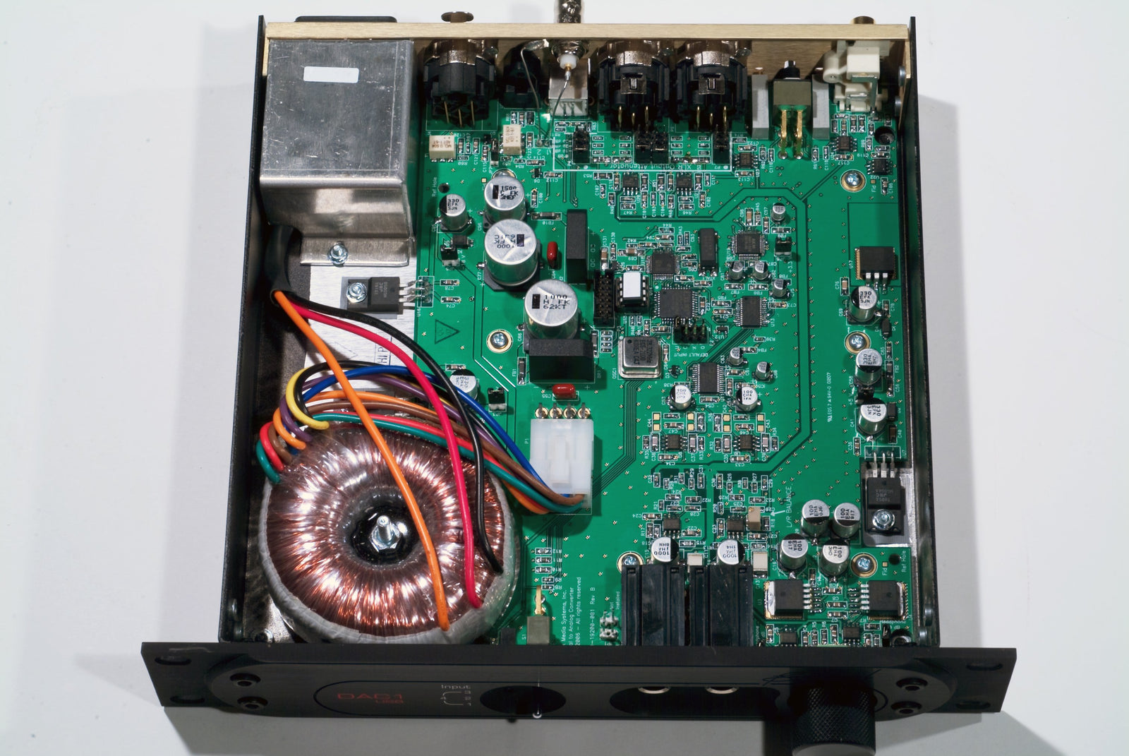
We chose 110 kHz because this is near the maximum frequency that the AD1853 can reliably operate in the 2x (88.2 kHz and 96 kHz) mode. We measured the performance of the AD1853 vs. sample frequency before choosing 110 kHz. At 110 kHz, the passband of our frequency-shifted AD1853 is 45.8 kHz. When combined with our outboard filters, the DAC1 is almost entirely free of images (alias effects). Given a different converter IC, we could choose a different conversion frequency (our asynchronous upsampling topology allows this flexibility).
Download PDF
Copyright© 2010 Benchmark Media Systems, Inc.
Also in Audio Application Notes
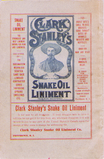

Audiophile Snake Oil
The Audiophile Wild West
Audiophiles live in the wild west. $495 will buy an "audiophile fuse" to replace the $1 generic fuse that came in your audio amplifier. $10,000 will buy a set of "audiophile speaker cables" to replace the $20 wires you purchased at the local hardware store. We are told that these $10,000 cables can be improved if we add a set of $300 "cable elevators" to dampen vibrations. You didn't even know that you needed elevators! And let's not forget to budget at least $200 for each of the "isolation platforms" we will need under our electronic components. Furthermore, it seems that any so-called "audiophile power cord" that costs less than $100, does not belong in a high-end system. And, if cost is no object, there are premium versions of each that can be purchased by the most discerning customers. A top-of-the line power cord could run $5000. One magazine claims that "the majority of listeners were able to hear the difference between a $5 power cable and a $5,000 power cord". Can you hear the difference? If not, are you really an audiophile?

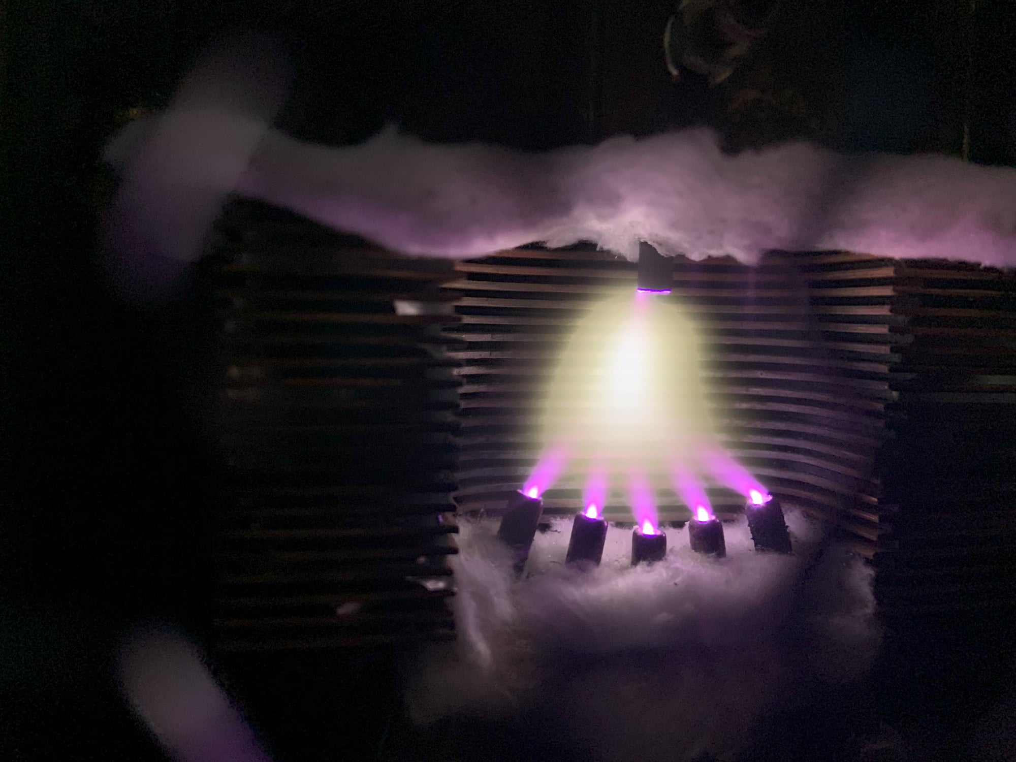
Making Sound with Plasma - Hill Plasmatronics Tweeter
At the 2023 AXPONA show in Chicago, I had the opportunity to see and hear the Hill Plasmatronics tweeter. I also had the great pleasure of meeting Dr. Alan Hill, the physicist who invented this unique device.
The plasma driver has no moving parts and no diaphragm. Sound is emitted directly from the thermal expansion and contraction of an electrically sustained plasma. The plasma is generated within a stream of helium gas. In the demonstration, there was a large helium tank on the floor with a sufficient supply for several hours of listening.

While a tank of helium, tubing, high voltage power supplies, and the smell of smoke may not be appropriate for every living room, this was absolutely the best thing I experienced at the show!
- John Siau

Audio Calculators
We have added an "Audio Calculators" section to our webpage. Click "Calculators" on the top menu to see more like these: