Jitter and its Effects

By John Siau and Allen H. Burdick
Introduction:
This paper addresses these questions:
- How and where do I measure jitter, and how do I eliminate it?
- How does sample clock jitter relate to interface jitter measured at the AES/EBU or SMPTE output connectors?
- How can we accurately measure jitter?
- Why does sample clock jitter have to be so low?
Much Confusion Exists over Jitter: How and Where to Measure It, and How to Eliminate It
The phase modulation effects of sample clock jitter in any A-to-D converter become a permanent part of your recording. For that reason, great effort has been invested eliminating sample clock jitter in the Benchmark A-to-D converters. A unique and proprietary Phase Lock Loop keeps the converters virtually free from sample clock jitter, under all operating conditions. Clock jitter at the converter’s sample and hold is typically 9 Pico-seconds RMS (9 trillionths of a second) measured over a bandwidth of 20 Hz to 12.288 MHz. Remember, sample clock jitter in either an A-to-D or D-to-A converter can have a devastating effect on the audio.
 Figure 1. - FFT Analysis of a Tightly Locked A-to-D Converter
How Does Sample-Clock Jitter Relate to Interface Jitter Measured at the AES/EBU or SMPTE Output Connectors?
Sample clock jitter cannot be measured at an AES/EBU or SMPTE output connector. The reason is simple: AES interface standards require bandwidth and rise-time limiting in order to reduce electromagnetic interference. As a result, the AES interface will add code-dependent jitter, which may be 100 to 1000 times greater than the jitter at the converter’s sample and hold. This is potentially inconsequential. This interface jitter accumulates after the audio is in the digital domain, and therefore, does not degrade the audio signal, provided it is removed prior to D-to-A conversion. But, unlike interface jitter, sample clock jitter cannot be removed. Therefore it is critical to measure the sample clock jitter by itself.
How Can We Accurately Measure Jitter?
Sample clock jitter can be isolated and measured to a resolution better than 2 pSec using a 16,000 point FFT analysis of the 24-bit digital audio output of an A-to-D converter. If, for instance, a -1 dBFS 10 kHz high purity test tone is connected to the analog input of an A-to-D converter, sample clock jitter of 16 pSec will produce spurious tones (side bands from the jitter’s phase modulation effect) which have a total energy of -123 dBFS. If the jitter energy is concentrated at a single frequency, as is often the case, two side bands will be produced, one on either side of the 10 kHz test tone. Each side band will have an amplitude of -129 dBFS. Although -129 dBFS is an extremely low level, it is still within the resolving ability of most 24-bit A-to-D converters. This is important because our ears act much like a super resolving FFT analyzer.

FIGURE 2. 100-kHz STOP-BAND ATTENUATION VS. JITTER AT THE CONVERTER CHIP
Why Does Sample-Clock Jitter Need to be so Low?
It can be easily demonstrated that most people have the ability to detect and identify tones which are buried 25 dB or more below white noise (A-Weighted). Therefore, it is important to keep jitter induced side bands nearly 25 dB below the A-Weighted THD+N of the converter, otherwise the jitter may become audible.
Jitter can only be considered totally inaudible if the worst case jitter induced sidebands are at least 23 dB below the A-weighted system noise. Above this level jitter may be audible or it may be masked by the program audio. At Benchmark our goal is to achieve totally inaudible levels of jitter.
The FFT analysis shown in Figure 1. demonstrates the ability of the BENCHMARK AD2402-96 to resolve tones as low as -140 dBFS. Note that in this test, the AD2402-96’s highest jitter induced side bands occur at 4 kHz and 16 kHz. These each measure at an extremely low -140 dBFS and indicate that jitter at 6 kHz (a common problem frequency) is below 5 Pico-seconds. The AD2402-96 has an idle channel THD+N of better than -117 dBFS (A-Weighted) and jitter induced side bands are held 23 dB below this level. It is this level of performance, which makes the AD2402-96 and the AD2404-96 (identical circuits) so unique.
Jitter Degrades Digital Anti-Alias Filters
The performance of oversampled A/D converters is highly dependent upon very precise digital filters. These digital filters provide a brick wall that stops unwanted high frequency signals. In the case of 44.1 kHz conversion, this brick wall filter is constructed such that it stops all frequencies above 22.05 kHz (one half of the sample rate). Frequencies above 22.05 kHz cannot be represented in a 44.1 kHz digital system. If these frequencies are not removed, aliasing will occur. When aliasing occurs, high frequency information is translated or folded back into the audio band.
Oversampled converters use digital filters to prevent aliasing, non-oversampled converters rely solely upon analog filters in front of the A/D sample and hold circuit. Analog filters require closely matched resistors and capacitors, parts with low temperature coefficients, and lots of space on a circuit board. A digital filter can easily outperform the best analog filter. Digital filter performance is generally limited only by the number of arithmetic operations that we are willing to perform for each sample of audio that passes through the filter. State of the art A/D converter ICs have digital filters that can achieve remarkable levels of performance. For example, at a 44.1 kHz sample rate, the digital anti-alias filter in the SONIC AD2K+ achieves 117 dB of attenuation at all frequencies between 24.44022 kHz and 2.798145 MHz while the response at 20.30364 kHz is -0.01 dB! However, this performance can only be achieved in the absence of jitter.
When a digital filter is designed, jitter is assumed to be zero. A digital filter consists of a series of delay elements, multipliers, and summing nodes. The delay elements are assumed to be identical in length. Jitter can and does change the length of time between successive samples of audio. As a result, the digital delay elements no longer represent equally spaced points in time. Jitter modulates the time interval between samples, and this can radically alter the response of the filter. For example, if converter clock in the SONIC AD2K+ or the AD2404-96 were derived directly from the AES/EBU receiver (as it is in many converter products) the stopband attenuation at 100 kHz would be degraded from 117 dB to only 28 dB. The 100 kHz signal that should have been removed is now splattered all over the audio band (see graphs above and below).
A second graph below shows the effect of jitter on the stop band attenuation with a 26-kHz input signal.
 FIGURE 3. 26-kHz STOP-BAND ATTENUATION VS. JITTER AT THE CONVERTER CHIP
Additional Information:
Additional information about jitter may be found at the following locations.
Jitter: Specification and Assessment in Digital Audio Equipment Julian Dunn, Presented at the 93rd AES Convention, October 1992
Jitter, Wikipedia
Jitter, Bob Katz, December 2007
Jitter Measurement Techniques, Audio Precision
Also in Audio Application Notes
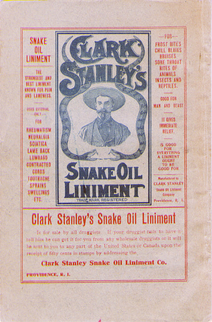

Audiophile Snake Oil
The Audiophile Wild West
Audiophiles live in the wild west. $495 will buy an "audiophile fuse" to replace the $1 generic fuse that came in your audio amplifier. $10,000 will buy a set of "audiophile speaker cables" to replace the $20 wires you purchased at the local hardware store. We are told that these $10,000 cables can be improved if we add a set of $300 "cable elevators" to dampen vibrations. You didn't even know that you needed elevators! And let's not forget to budget at least $200 for each of the "isolation platforms" we will need under our electronic components. Furthermore, it seems that any so-called "audiophile power cord" that costs less than $100, does not belong in a high-end system. And, if cost is no object, there are premium versions of each that can be purchased by the most discerning customers. A top-of-the line power cord could run $5000. One magazine claims that "the majority of listeners were able to hear the difference between a $5 power cable and a $5,000 power cord". Can you hear the difference? If not, are you really an audiophile?

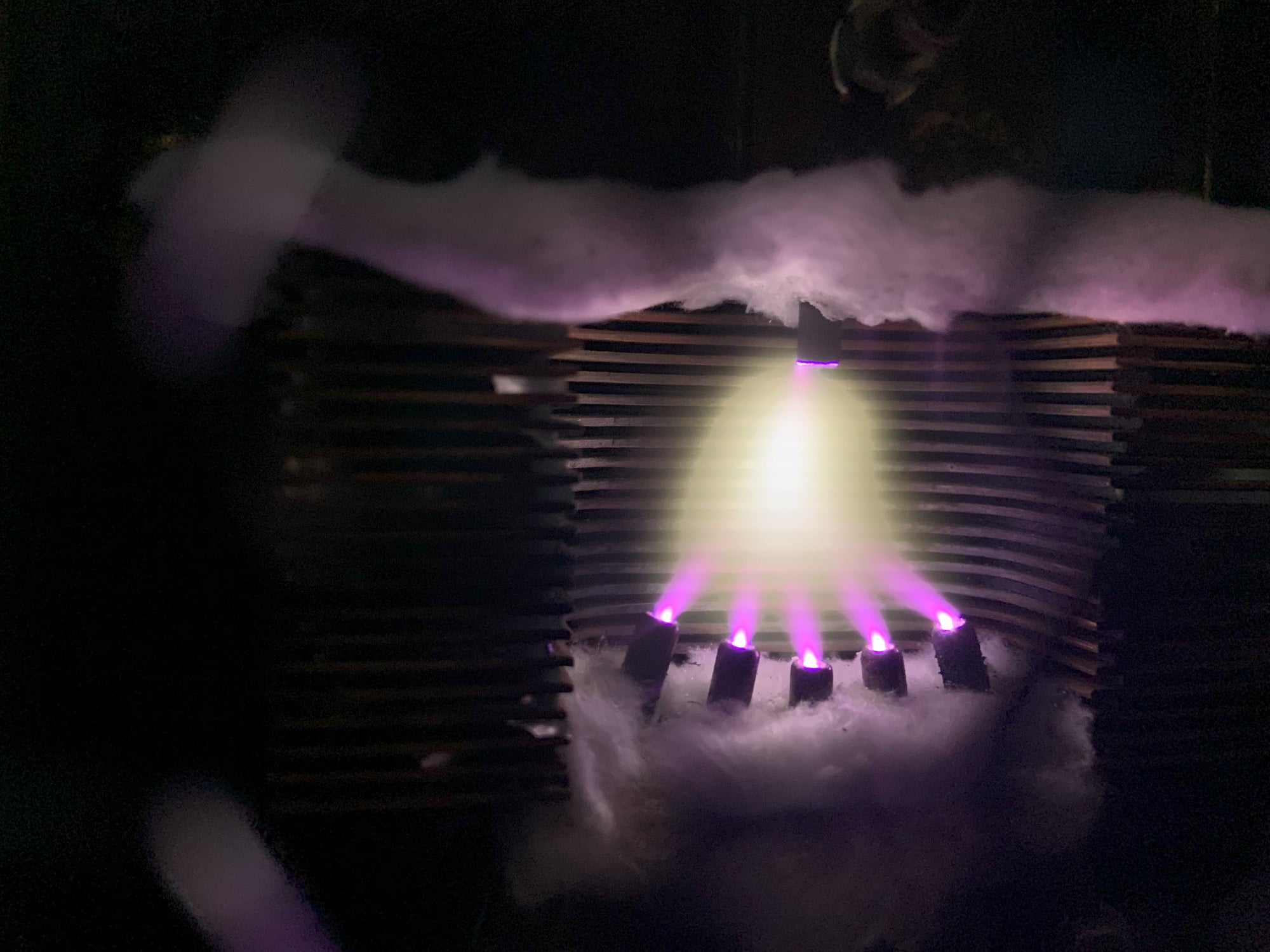
Making Sound with Plasma - Hill Plasmatronics Tweeter
At the 2023 AXPONA show in Chicago, I had the opportunity to see and hear the Hill Plasmatronics tweeter. I also had the great pleasure of meeting Dr. Alan Hill, the physicist who invented this unique device.
The plasma driver has no moving parts and no diaphragm. Sound is emitted directly from the thermal expansion and contraction of an electrically sustained plasma. The plasma is generated within a stream of helium gas. In the demonstration, there was a large helium tank on the floor with a sufficient supply for several hours of listening.

While a tank of helium, tubing, high voltage power supplies, and the smell of smoke may not be appropriate for every living room, this was absolutely the best thing I experienced at the show!
- John Siau

Audio Calculators
We have added an "Audio Calculators" section to our webpage. Click "Calculators" on the top menu to see more like these: