Box-to-Box Phase Accuracy of Benchmark DAC1 and DAC2 Converters

Phase Accuracy in an Asynchronous Environment

Two or more Benchmark DAC1 or DAC2 converters can be used together in phase-coherent multichannel audio systems even though their internal clocks are not synchronized. This seems to defy logic, but an examination of the system details reveals why this is possible.
Benchmark D/A Converters can be Used Together in Phase-Coherent Systems
Our bench tests show that if identical signals are fed to two separate DAC1 boxes, the outputs will be precisely in phase with each other, at sample rates up to about 110 kHz. Below this sample rate, the L to R differential phase response of a single DAC1 is almost identical to the differential phase between the outputs of two separate DAC1 boxes.
Similar tests show that two or more DAC2 converters can be used to create phase-coherent multi channel systems at any sample rate. Please note that the time delay through a DAC1 is not the same as a DAC2. This means that the two generations of Benchmark D/A converters should not be mixed when phase-coherence is required.
Benchmark converters achieve nearly perfect box-to-box phase matching without using a separate clock input. This note discusses some of the technical details that contribute to this box-to-box phase matching.
ASRC System in the DAC1
The DAC1 uses an AD1896 asynchronous sample rate converter (ASRC) to isolate the incoming digital audio clock from a free-running low-jitter conversion clock. Every DAC1 has its own free-running master clock. These free-running clocks do not need to be synchronized in order to have a predictable delay through the system. The DAC1 uses the AD1896 to upconvert the audio to a sample rate of about 111 kHz. When upconverting, the AD1896 has a fixed delay that is a function of the input sample rate only. The phase relationship between the input and outputs clock will not change the delay through the SRC. The SRC filter coefficients are always selected to maintain a constant delay from the average phase of the input clock signal. The averaging function prevents jitter artifacts, and is one of 3 significant advantages provided by an upsampling SRC topology.
In a multi-channel system, the digital signals feeding multiple DAC1 converters are all derived from the same clock, and are in phase. However, the internal conversion clocks (inside the DAC1 boxes) are all running independently and yet phase accuracy is maintained (see the plots in the manual). The phase accuracy between two DAC1 boxes is only a function of the frequency matching of the two independent fixed-frequency conversion oscillators. These are crystal oscillators and are actually much more closely matched than they need to be. The clock frequencies are matched to +/- about 50 PPM (+/- 0.005%), and if we do the math, the worst-case miss-match will produce a phase error of only +/- 0.004 degrees at 20 kHz! The analog circuits (and the measurement equipment) have orders of magnitude more phase error than the SRC & D/A conversion systems in the DAC1!
DAC1 Converters can be used in Multichannel Systems at Sample Rates up to 100 kHz
Multiple DAC1 boxes are phase accurate up to an input frequency of 110 kHz. We do not claim phase accuracy between DAC1 boxes running at 176.4 or 192 kHz.
The Math
The delay on the 110 kHz side of the SRC is 1.01 ms +/- 50 ppm. The +/- 50 ppm variation is due to the +/- 50 ppm variation in the oscillator used for the 110 kHz D/A conversion clock.
50 ppm is 0.00005
0.00005*1.01 ms = 50.5 ns
50.5 ns is equivalent to moving the position of a microphone by 0.00005 feet, and is equivalent to the electrical delay through a 25 foot cable.
At 20 kHz, +/- 50.5 ns is:
50.5E-9*20000*360=0.36 degrees (at 20 kHz)
This +/- 0.36 degree variation is insignificant, even when the channels are summed.
The amplitude error after summing is: 20*Log((cos(0.36*2)+cos(0))/2)=-0.00035 dB at 20 kHz
What about comb filtering? The first null in the comb filter will occur no lower than: 1/(2*50.5 ns/2)= 19.8 MHz
The bandwidth of 96 kHz digital audio is limited to 48 kHz, so a null at 19.8 MHz is of no consequence.
DAC2 Converters can be used at any Sample Rate in a Multichannel System
The DAC2 system is also asynchronous, but due to improved technology, it maintains box-to-box phase accuracy at all input sample rates.
Also in Audio Application Notes
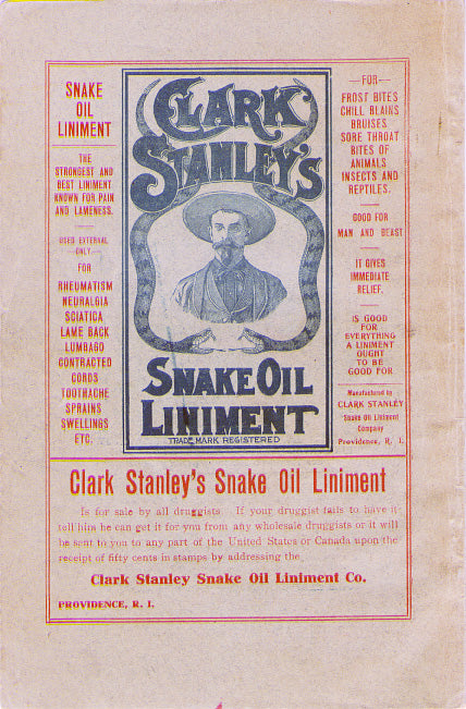

Audiophile Snake Oil
The Audiophile Wild West
Audiophiles live in the wild west. $495 will buy an "audiophile fuse" to replace the $1 generic fuse that came in your audio amplifier. $10,000 will buy a set of "audiophile speaker cables" to replace the $20 wires you purchased at the local hardware store. We are told that these $10,000 cables can be improved if we add a set of $300 "cable elevators" to dampen vibrations. You didn't even know that you needed elevators! And let's not forget to budget at least $200 for each of the "isolation platforms" we will need under our electronic components. Furthermore, it seems that any so-called "audiophile power cord" that costs less than $100, does not belong in a high-end system. And, if cost is no object, there are premium versions of each that can be purchased by the most discerning customers. A top-of-the line power cord could run $5000. One magazine claims that "the majority of listeners were able to hear the difference between a $5 power cable and a $5,000 power cord". Can you hear the difference? If not, are you really an audiophile?

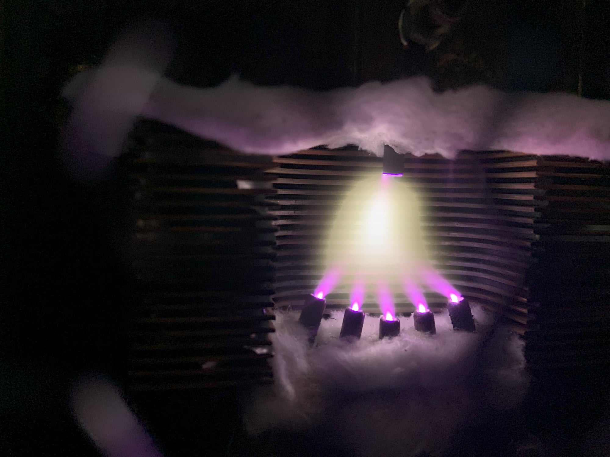
Making Sound with Plasma - Hill Plasmatronics Tweeter
At the 2023 AXPONA show in Chicago, I had the opportunity to see and hear the Hill Plasmatronics tweeter. I also had the great pleasure of meeting Dr. Alan Hill, the physicist who invented this unique device.
The plasma driver has no moving parts and no diaphragm. Sound is emitted directly from the thermal expansion and contraction of an electrically sustained plasma. The plasma is generated within a stream of helium gas. In the demonstration, there was a large helium tank on the floor with a sufficient supply for several hours of listening.

While a tank of helium, tubing, high voltage power supplies, and the smell of smoke may not be appropriate for every living room, this was absolutely the best thing I experienced at the show!
- John Siau

Audio Calculators
We have added an "Audio Calculators" section to our webpage. Click "Calculators" on the top menu to see more like these: