Buy one component and save 10% on up to 2 cables. Buy 2 components and get 4 free cables. Free shipping on USA orders over $700.
Buy one component and save 10% on up to 2 cables. Buy 2 components and get 4 free cables. Free shipping on USA orders over $700.
Using the HPA-1 as a Long-Lines Driver
by Benchmark Media Systems January 15, 1997
By Allen H. Burdick
Converting the HPA-1 to a long lines driver.
Introduction
The high current output configuration of the HPA-1 is ideal for use as a transformerless long lines driver. Conversion of the unit for this purpose, source, transmission line, and termination considerations will be discussed.
General
The HPA-1 is a two channel inverting amplifier card with current boost buffers that provide an output current capability of 300 mA (each side). Independent channels give the HPA-1 the configuration flexibility needed for a long lines driver.
A Basic Configuration Change
As supplied, the HPA-2 has a variable gain output. Since we desire to use the unit as a transformerless line driver we will typically want a fixed gain. We will convert the gain of the HPA-1 to unity (be sure to convert both sides).
Figure 1.0 shows the modifications necessary, they are enclosed in boxes. Replace the potentiometer with a jumper and feedback resistor combination. The feedback resistor needs to be a 10 k 1% metal oxide type. If you desire to retain variable gain, do so with careful thought. In the unbalanced example to follow, the gain pot can be left in the input side, but a unity gain inverter must be created on the opposite leg. The gain pot may be retained for both sides of the HPA in both balanced input examples.
We also recommend removing the TRS jack, replacing it with a XLR type and mounting the board in a chassis, with double sided sticky foam tape and a tie wrap.
Drive Configurations
Determine whether the source that will be driving the "Long Line Driver" is a balanced or an unbalanced source and then use the proper circuit shown below. Please note that these drawings specify the now obsolete HPA-1. These drivers will perform with outstanding clarity using the new HPA-1. The indicated 30 O output resistors are not present in the new HPA-1 and will have to be added externally to the HPA-1s circuit board.
Unbalanced Source
When driving from an unbalanced source, feed the signal into the "Left" input. The other input is fed from the "Left" output, prior to the build out resistor. I.e. tie the "Right" input, post pin 1, to the "left" output (pin 7 of the buffer) of the HPA-1. This can be done with a small jumper wire, located on the bottom of the board. This jumper makes the right channel follow the left creating a differential or "balanced" output. The balanced signal output is taken from the two build-out resistors. Note the polarity inversion: the + output comes from where the ring output previously connected and output from the tip location.
Electronically Balanced Source
Electronically balanced sources and transformer sources are very easy to hookup. Follow the diagrams below. Note the polarity inversion: the + output comes from where the ring output previously connected and output from the tip location.
Line Considerations
Transmission lines have capacitance that must be fed current. The higher the frequency, and output voltage swing, the higher the current requirement. Using a standard NE5532 operational amplifier, (commonly used in output stages) the nominal length of transmission line (Belden 8451 @ 32 pF/foot) that can be driven to full output at 30 kHz is 300 feet. Longer lines require more than the 40 mA current limit of a NE5532. This is the rational for the conversion of the HPA-1 to a long lines driver. Additionally, by reducing the inter conductor capacitance, longer lines may be driven with the same amplifier current limit. For instance, by using Mogami 2574 cable with its 6 pF/foot capacitance 1000' of cable can be driven with the straight NE5532. A current boosted NE5532 (modified HPA-1) can drive 2250' of Belden 8451 to full output level at 30 kHz, and 7,500' of the Mogami cable to the same level @ 30 kHz, over six times the length of a straight NE5532.
Terminations
Terminations are not needed, nor are they desirable at cable lengths out to 3000' (1/10 l @ 20 kHz). Beyond that distance a true transmission line should be established. A 60 resistor across the line at the receive end will terminate the line as a true power matched line. There will be a 6 dB drop in level as a result of termination. High frequency equalization may be necessary for extremely long lines.
Receive Amplifiers
Since the drive amplifier does not have an output transformer, one may need to be present at the input of the receive device. If the equipment does not have a transformer built into its circuit, an external transformer will in all probability need to be added. We recommend those manufactured by Reichenbach Engineering or Jensen Transformers.
For additional information on transmission lines, see "A Clean Audio Installation Guide™" a Benchmark Media Systems, Inc. application note.
Leave a comment
Comments will be approved before showing up.
Also in Audio Application Notes

How Loud is the Distortion from Your Power Amplifier?
by John Siau August 08, 2025
Would you put a Washing Machine in your Listening Room?
If the answer is no, you may be surprised to discover that the distortion produced by your power amplifier may be louder than the noise produced by a major appliance.
Don't believe me? Take a look at Stereophile's test reports:
We selected 7 power amplifiers from Stereophile's top list of recommended amplifiers.
We took Stereophile's "THD+N vs. Power" plots for each, and replotted the data in a format that shows the loudness of the THD+N at the listening position.
The results are shocking!
Amplifier THD+N is louder than expected!
The distortion from your amplifier may be louder than a washing machine on the spin cycle, or it may be totally silent. How does yours perform? The answer is hidden in Stereophile's THD+N plots.
This application note reveals the hidden truth:
"The Distortion from your Power Amplifier may be Louder than a Washing Machine!"
I know, it sounds crazy, but this is what the measurements show!

Interpolator Overload Distortion
by John Siau November 20, 2024
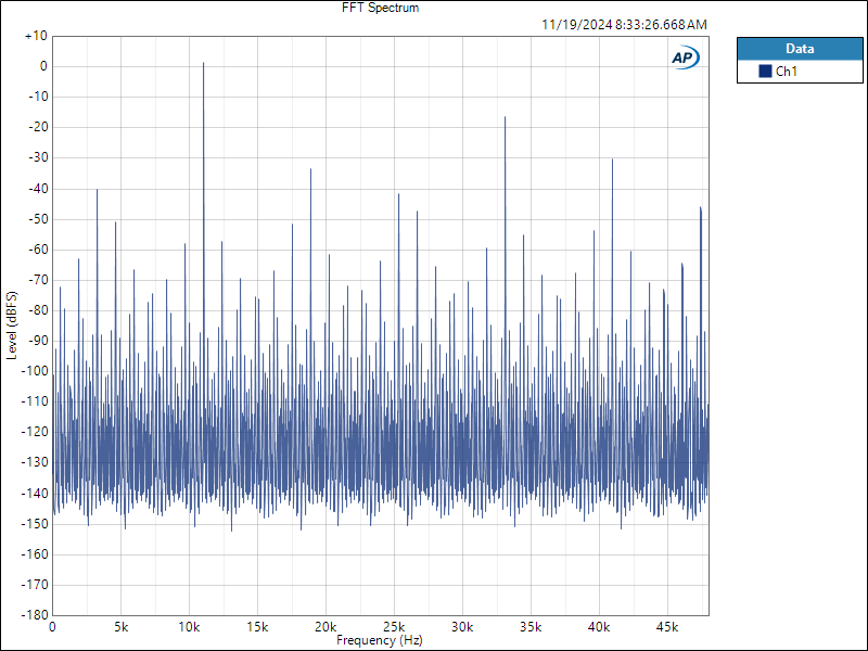
Most digital playback devices include digital interpolators. These interpolators increase the sample rate of the incoming audio to improve the performance of the playback system. Interpolators are essential in oversampled sigma-delta D/A converters, and in sample rate converters. In general, interpolators have vastly improved the performance of audio D/A converters by eliminating the need for analog brick wall filters. Nevertheless, digital interpolators have brick wall digital filters that can produce unique distortion signatures when they are overloaded.
10% Distortion
An interpolator that performs wonderfully when tested with standard test tones, may overload severely when playing the inter-sample musical peaks that are captured on a typical CD. In our tests, we observed THD+N levels exceeding 10% while interpolator overloads were occurring. The highest levels were produced by devices that included ASRC sample rate converters.

Audiophile Snake Oil
by John Siau April 05, 2024
The Audiophile Wild West
Audiophiles live in the wild west. $495 will buy an "audiophile fuse" to replace the $1 generic fuse that came in your audio amplifier. $10,000 will buy a set of "audiophile speaker cables" to replace the $20 wires you purchased at the local hardware store. We are told that these $10,000 cables can be improved if we add a set of $300 "cable elevators" to dampen vibrations. You didn't even know that you needed elevators! And let's not forget to budget at least $200 for each of the "isolation platforms" we will need under our electronic components. Furthermore, it seems that any so-called "audiophile power cord" that costs less than $100, does not belong in a high-end system. And, if cost is no object, there are premium versions of each that can be purchased by the most discerning customers. A top-of-the line power cord could run $5000. One magazine claims that "the majority of listeners were able to hear the difference between a $5 power cable and a $5,000 power cord". Can you hear the difference? If not, are you really an audiophile?

