Buy one component and save 10% on up to 2 cables. Buy 2 components and get 4 free cables. Free shipping on USA orders over $700.
Buy one component and save 10% on up to 2 cables. Buy 2 components and get 4 free cables. Free shipping on USA orders over $700.
Building the L-R Null Test Set
by Benchmark Media Systems February 01, 1997
By Allen H. Burdick
Introduction
In the process of broadcast matrix encoding and decoding, balancing amplitudes between the two channels of a stereo audio path is very necessary. It is necessary for the maintenance of proper headroom, dynamic range and, of course, separation.
From time to time, repair and maintenance must be performed on equipment. Returning the entire chain to a balanced condition when placing the equipment back in service, is very desirable. Most broadcast engineers have balanced a chain at the stereo generator using the L-R method. But why not balance the output of each piece of equipment throughout the studio and eliminate the trip to the transmitter? It could mean eliminating late nights, and for those who don't go off the air, it may be the only option.
While recording studios do not face the same problems as the broadcaster, much of what is recorded in a studio is broadcast. This technique, therefore, is also applicable to the maintenance of a final stereo path in a recording facility.
Review
Measuring the amplitudes of the two channels using side by side VU or PPM meters at best yields a balance to within a dB or two. This is not close enough for today's standards. Vastly improved resolution is possible by measuring the difference between the two identical mono signals by performing an L-R null at each point along the chain. The adjustments are made using mono program material in the signal chain. The degree of balance achieved will allow you to be confident that the listener's stereo hasn't been degraded by the process.

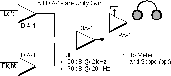
Fig 1.- L-R Test Set
The test set uses well-trimmed difference amplifier circuits. The noise floor is the practical limit to the depth of null that can be achieved with identical signals. This property allows signal amplitudes to be matched to exceedingly small differences, 1 part in 10 to the 5th, or better. Additionally this type of measurement will allow an engineer to determine which pieces of equipment have differing inter channel time delays or phase shift, the other property that upsets channel separation.
Construction
The L-R test set is easily constructed with three Benchmark Media DIA-1 differential input modules and some form of wide band AC voltmeter. The test set is shown in Figure 1. Two of the differential inputs are used to interface to balanced lines while the third is the L-R amplifier. We suggest building the DIA-1s into a Benchmark IFA box, and powering the set from a Benchmark PS-1 ±16 volt wall mount power supply. The drawings presented here include the now obsolete HPA-1 headphone amplifier. The new HPA-2 will perform significantly better than the older HPA-1 and is highly recommended.
Once you have the differential amplifiers installed in a chassis and wired you should power up to verify that everything is working and wiring shorts haven't crept into the project.
Even though the DIAs were precisely adjusted at the factory, the one used to measure L-R null will have to be re-adjusted. This is because the gains of the two input DIAs, while extremely close, are not perfectly identical. A re-trim will adjust for that difference. You may want to include a headphone amplifier to listen to the nulling, as well. The following is the recommended CMR adjustment setup to perform the L-R circuit readjustment.
Setting up the L-R Circuit
The common mode rejection trims are part of a passive bridge. Adjustment of the trims is an adjustment of the balance of this bridge. In this case we are adjusting for the slightly different gains of the input DIA-1s.

Fig 2 - L-R Circuit Adjustment
Feed a balanced signal of +20 dBu into both inputs of the test set. Send a 2 kHz signal to the input and adjust the resistive portion of the third DIA-1s bridge for a minimum audio output. It is very helpful to watch the audio signal from the meter output on an oscilloscope, which in turn should be synchronized to the signal source. This will allow you to quickly see the phase-amplitude nulls as they take place. This is one place where a digital voltmeter is almost impossible to use. The easiest meter type to use is a logarithmic type. DBX and Valley People have manufactured these items in the past, and may be available on the used market. If you can't put your hands on one of these, a conventional AC VTVM will work. Once a minimum resistive trim has been achieved, null the capacitive trim.
Two or three iterations between these controls should be sufficient to achieve the best broadband null possible. A null of better than 100 dB at 200 Hz, and better than 75 dB at 20 kHz, is usually achievable. Unfortunately, it is almost impossible to maintain this precise a null over much of a temperature range. A degradation of up to 10 dB may be expected.
Using the Test Set
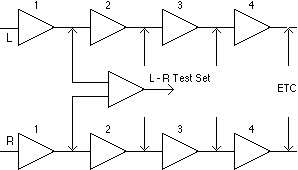
Using the test set is straight forward. Place the audio console into mono mode. If this is not available, you will have to add this capability to the console. Using program material move through the chain and make sure that the gains of the left channels are all at unity by using the L-R test set to compare the input level with the output level. You will not be able to achieve a perfect null in this adjustment since there will be time delay through the equipment. However the best null will set the amplitudes at a precision unity gain. Next balance the amplitudes between the two channels of each piece of equipment, making sure to only adjust the right channel gains. Finally adjust the L-R null at the stereo generator. This completes the chain set-up.

Fig 3. - Chain Set-Up Using L-R Test Set
As implied above, it is possible to measure the differential phase shift between channels of equipment by measuring the depth of null and doing a small computation. Additionally it is also possible to add phase equalization to the audio chain and correct for signal delay differences between the channels. We may examine this in a future app-note.
Leave a comment
Comments will be approved before showing up.
Also in Audio Application Notes

How Loud is the Distortion from Your Power Amplifier?
by John Siau August 08, 2025
Would you put a Washing Machine in your Listening Room?
If the answer is no, you may be surprised to discover that the distortion produced by your power amplifier may be louder than the noise produced by a major appliance.
Don't believe me? Take a look at Stereophile's test reports:
We selected 7 power amplifiers from Stereophile's top list of recommended amplifiers.
We took Stereophile's "THD+N vs. Power" plots for each, and replotted the data in a format that shows the loudness of the THD+N at the listening position.
The results are shocking!
Amplifier THD+N is louder than expected!
The distortion from your amplifier may be louder than a washing machine on the spin cycle, or it may be totally silent. How does yours perform? The answer is hidden in Stereophile's THD+N plots.
This application note reveals the hidden truth:
"The Distortion from your Power Amplifier may be Louder than a Washing Machine!"
I know, it sounds crazy, but this is what the measurements show!

Interpolator Overload Distortion
by John Siau November 20, 2024
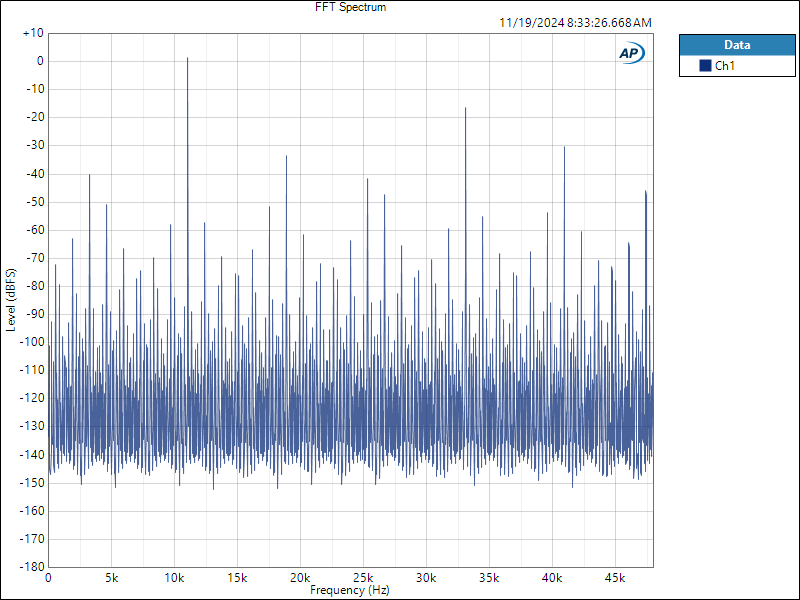
Most digital playback devices include digital interpolators. These interpolators increase the sample rate of the incoming audio to improve the performance of the playback system. Interpolators are essential in oversampled sigma-delta D/A converters, and in sample rate converters. In general, interpolators have vastly improved the performance of audio D/A converters by eliminating the need for analog brick wall filters. Nevertheless, digital interpolators have brick wall digital filters that can produce unique distortion signatures when they are overloaded.
10% Distortion
An interpolator that performs wonderfully when tested with standard test tones, may overload severely when playing the inter-sample musical peaks that are captured on a typical CD. In our tests, we observed THD+N levels exceeding 10% while interpolator overloads were occurring. The highest levels were produced by devices that included ASRC sample rate converters.

Audiophile Snake Oil
by John Siau April 05, 2024
The Audiophile Wild West
Audiophiles live in the wild west. $495 will buy an "audiophile fuse" to replace the $1 generic fuse that came in your audio amplifier. $10,000 will buy a set of "audiophile speaker cables" to replace the $20 wires you purchased at the local hardware store. We are told that these $10,000 cables can be improved if we add a set of $300 "cable elevators" to dampen vibrations. You didn't even know that you needed elevators! And let's not forget to budget at least $200 for each of the "isolation platforms" we will need under our electronic components. Furthermore, it seems that any so-called "audiophile power cord" that costs less than $100, does not belong in a high-end system. And, if cost is no object, there are premium versions of each that can be purchased by the most discerning customers. A top-of-the line power cord could run $5000. One magazine claims that "the majority of listeners were able to hear the difference between a $5 power cable and a $5,000 power cord". Can you hear the difference? If not, are you really an audiophile?

