Most people have seen the CE mark on electronic equipment, but few have had the opportunity to witness the tests that are required to conform to the CE specifications. This post takes the reader on a behind-the-scenes photo-tour of the CE tests of Benchmark's new AHB2 power amplifier.
The CE mark is a manufacturer's declaration that the product has passed a comprehensive set of tests to evaluate the ability of the product to operate in close proximity to other electronic products. This means that the product must be immune to interference caused by nearby products, and that it must not emit excessive interference that could cause problems to nearby products.
There are two parts to the CE tests - immunity and emissions.This photo-tour focuses on the immunity tests.
Photo 1 - Immunity to Radio Interference

Photo 1 shows the AHB2 being exposed to high levels of Radio Frequency (RF) interference.
The transmitting antenna (which looks like a giant egg beater) is positioned in front of the AHB2. The spherical object on top of the AHB2 is an RF field strength probe. During these tests, the radio interference is swept over a wide range of frequencies while the product is rotated to maximize exposure on each of four sides.
As a professional product, the AHB2 must continue to operate at full performance under these test conditions. In contrast, consumer products are subjected to lower RF levels and are permitted some loss in performance.
These tests are performed in a shielded room. The high-power radio signals used in these tests must not be allowed to escape the room where they could interfere with radio communications systems. RF absorption panels on the walls help minimize reflections of the RF energy to improve the uniformity of the interfering signal.
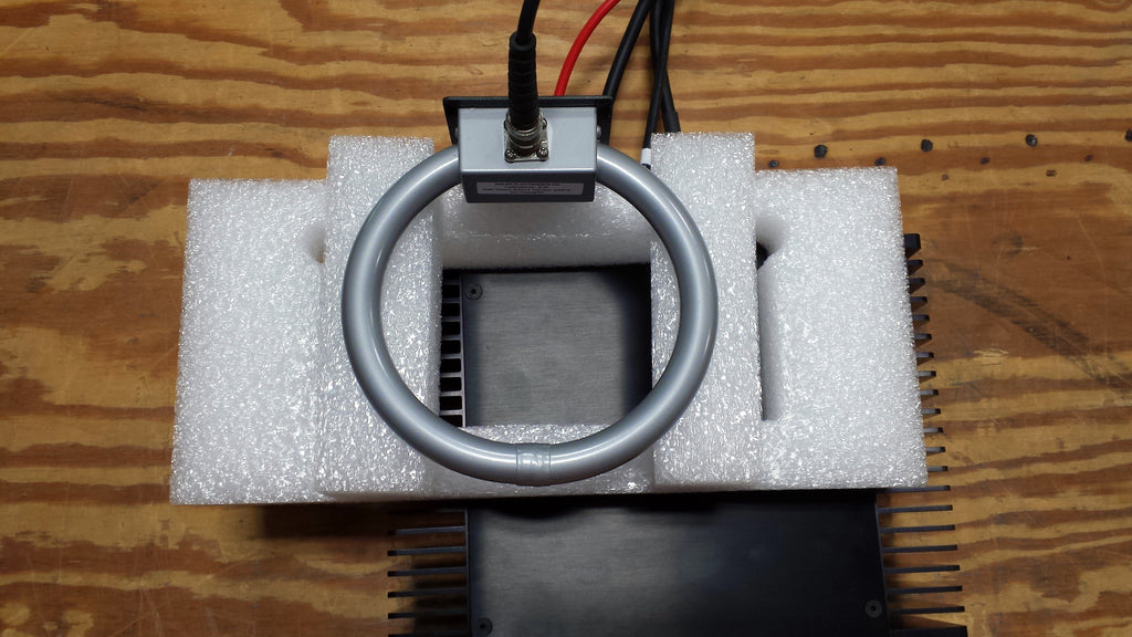
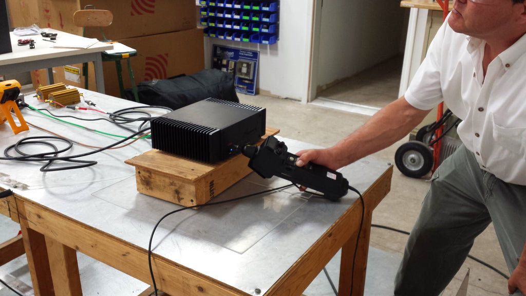
Photo 2 - Immunity to Magnetic Fields

Photo 2 shows the AHB2 being exposed to a magnetic field.
The coil induces a magnetic field at frequencies between 50 Hz and 15.75 kHz to test for magnetic immunity. The coil is held at a precise distance while scanning all surfaces of the device under test. The AHB2 has two layers of magnetic shielding, and easily passes this series of tests.
This is part of a special series of tests for rack-mounted professional products. Consumer products are subjected to lower magnetic field levels and are only tested at 50 or 60 Hz. This difference underscores the importance of selecting professional products for use in the studio.
Photo 3 - Immunity to Electrostatic Discharge

Photo 3 shows a technician zapping an AHB2 with a high-voltage discharge. All sides of the product must be able to withstand direct and indirect discharges, and the product must continue to function normally. This test is is designed to insure that your speakers do not make a noise if someone walks across the carpet and touches the power amplifier.
Consumer products are subjected to the same tests but are allowed non-permanent malfunctions. A pop or crackle from the speakers would be considered acceptable from a consumer power amplifier. The standards allow a complete shutdown or reboot of consumer-grade products as long as no permanent damage is sustained.
Photo 4 - Immunity to Power Line Surges

Photo 4 shows some of the equipment used to expose the product to power line surges, dips, and brownouts.These test standards minimize the chances that a product will fail due to power line surges.
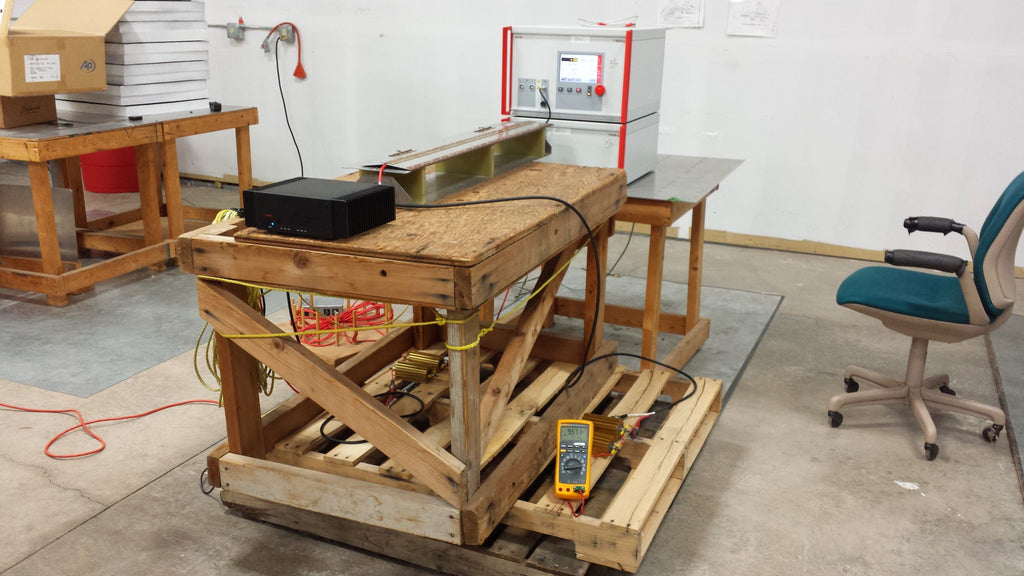
Photo 5 - Immunity to Conducted Interference

Photo 5 shows some of the apparatus used to inject interfering signals onto the input and output cables of the AHB2. This test shows capacitive coupling of an interfering signal. Other tests use direct injection, while others use magnetic coupling. Together, these test are designed to cover all possible means of interference.
CE tests vary by product type, intended application, and intended environment. See The CE Mark - What Does it Mean, and Why Should I Care? for more background on the CE tests.


