Link your audio products together with trigger cables
Benchmark has created a bi-directional 12 Volt trigger interface that is compatible with almost every trigger input and output. This interface can be used to connect Benchmark products together so that they will power up and down in a sequenced fashion. This same interface can be connected to the trigger inputs and outputs on other brands of audio products. This application note describes some typical configurations and it includes the full technical details of the Benchmark trigger system. Most users will be able to connect their audio components together without the need to worry about the details in the "Technical Description" section.
Benchmark Products with Trigger I/O Connections
The Benchmark bi-directional 12 Volt trigger system is included on the following Benchmark products:
- DAC2 HGC - D/A Converter (one trigger I/O connector)
- DAC2 DX - D/A Converter (one trigger I/O connector)
- DAC2 L - D/A Converter (one trigger I/O connector)
- AHB2 - Power Amplifier (two trigger I/O connectors)
Typical Configurations:
- DAC2 (trigger I/O) <> AHB2 (trigger I/O)
- DAC2 (trigger I/O) <> AHB2 (trigger I/O) <> AHB2 (trigger I/O)
- DAC2 (trigger I/O) > Power Amplifier (trigger in)
- Preamplifier (trigger out) > DAC2 (trigger I/O) > Power Amplifier (trigger in)
- DAC2 (trigger I/O) >Preamplifier (trigger in), Preamplifier (trigger out) > Power Amplifier (trigger in)
Trigger Connector and Cable:

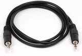

- Connecting cables may be three conductor 1/8" (TRS) or two conductor 1/8" (TS). The ring connection is not used.
- Trigger I/O jack is 1/8" TRS
- Tip = +12 V Trigger Signal
- Ring = No Connection
- Sleeve = Chassis Ground
Trigger Bus - Technical Description
- Trigger bus can function as a trigger output and can drive almost any 12 V trigger input.
- Trigger bus can automatically function as a trigger input when driven by almost any DC trigger output (having a positive voltage greater than 5 V, and less than 30 V).
- Trigger logic incorporates delays to minimize pops and clicks when devices power up and down. Benchmark products are designed to follow this power-up sequence:
- Analog and digital sources turn on
- Preamplifiers and signal processors turn on
- Power amplifiers turn on
- Power-down sequence is the reverse of the power-up sequence.
- Multiple Benchmark products can be wired in parallel on one trigger bus. Multiple non-Benchmark trigger inputs can be added to the bus. Up to one non-Benchmark trigger output can be added to the bus.
- If any Benchmark product on the trigger bus is turned on, all other Benchmark and non-Benchmark products will follow.
- The first Benchmark product turned on becomes the "initiating device". All other Benchmark devices on the bus automatically become "slave devices" and will follow the actions of the "initiating device". Any non-Benchmark trigger inputs attached to the bus will also slave to the actions of the "initiating device". If the "initiating device" turns off, all slaves will follow.
- The trigger jack on an "initiating device" will deliver 12V at up to 200 mA to turn on all "slave devices" connected to the trigger bus. This output is current limited to 200 mA at 12 V and is limited to 40 mA into a short-circuit (to ground). This output is driven by the "initiating device" whenever the system is on.
- If a Benchmark product is acting as a "slave device", it will turn off whenever the trigger bus voltage is less than 1.26 Volts for a period of 1/4 second.
- If the trigger bus is low (less than 1.26 V), for more than 2 seconds, Benchmark devices will assume all devices on the bus are off. No Benchmark device can become an "initiating device" until the bus has been low for at least 2 seconds. This 2-second waiting period insures that all power-down sequences have completed.
- The "initiating device" will monitor its own trigger output signal and release the 12 Volt output if an overload is detected. An overload is any condition that holds the trigger line at or below 1.26 V while the 12 Volt output is enabled. Monitoring will begin 2 seconds after applying the 12 Volt output signal. This 2-second delay allows short-term overloading while relays are firing and systems are initializing. Overloads detected in the first 2 second will not turn off the "initiating device". Overloads detected after the first 2 seconds will shut down the "initiating device". Overloads detected after the first 2 seconds indicate that a slave device has requested a system power down sequence.
- Signal source devices must turn on before power amplifiers. The DAC2 and DAC3 are a signal source device. If the DAC is turned on by a user, the trigger output will be applied after a 1/2 second delay. This 1/2 second delay allows the DAC circuits to stabilize before turning on the power amplifier. Audio will remain muted for an additional 1/2 second.
- Signal source devices must wait for power amplifiers to turn off before completing their power-down sequence. Signal source devices should immediately mute when the trigger bus is low for more than 1/4 second. This should also initiate the power-down sequence within the source device (if applicable). The source device should not produce a pop at an analog output for at least 10 seconds. In many cases this implies that the source device will remain in a standby mode (outputs muted, all analog output circuits active) for at least 10 seconds. The display should immediately show a response to the user's request to shut down.
- Benchmark power amplifiers will immediately respond to a high trigger signal (> 2.7 Volts). The amplifier will remain muted until stable.
- Benchmark power amplifiers will respond to a low trigger signal having a duration of at least 1/4 second. At the end of 1/4 second, the power amplifier will mute and begin powering down.
- "Slave devices" can force a system shutdown by pulling the trigger bus below 1.26 Volts. The trigger circuit in the DAC2 or DAC3 will pull the bus below 0.8 V. This pull-down circuit is current limited to 0.5 A.
- If a Benchmark product is off and a DC voltage (2.7-30 V) is externally applied to the trigger jack, the jack will function as a trigger input. Under these circumstances, the product will turn on in a muted condition, and remain muted for 1/2 second to minimize any system turn-on transients. After the 1/2 second mute interval has elapsed, the product will begin normal operation. The trigger jack will continue to act as an input, and product will mute 1/2 second after the loss of an externally applied trigger (input voltage under 1.26 V). The product will shut down completely 1 second after the loss of trigger.
- Benchmark devices draw 0.44 mA at 12V while the trigger jack is functioning as an input.
- If the trigger port is acting as an input, the externally-applied DC voltage must be removed, and the product must return to an off state, before the trigger jack can act as an output.
- The trigger jack is protected against short circuits and overloads. Output current is limited to 40 mA at 0 V and 200 mA at 12 V. Current limiting is built into the LDO regulator that supplies the trigger voltage.
- The trigger jack is protected against reverse voltage. A 1A diode protects against reverse voltages up to -100 V.
- The trigger jack will tolerate +30 V continuous.
- Trigger detect logic has a 15 Hz low-pass filter and peak detector. Additional digital logic will filter out non-DC signals (pulses shorter than 125 ms) on the trigger input. Benchmark products will remain in the current state unless the trigger is low for more than 125 ms.
- Trigger input is ESD protected.


