Power Supplies in Audio D/A Converters
The Benchmark DAC2 is an audio digital-to-analog converter. This application note explains the power supply configuration inside Benchmark's DAC2 D/A converter. In part 1 of this series we discussed the importance of the analog section of an audio converter. In part 2 we discussed the unique high-headroom digital processing chain inside the DAC2. The analog and digital systems each contribute toward Benchmark's overall goal of transparent musical reproduction, but this goal can only be reached when these systems are supported by a well-designed power supply system. Power supplies can adversely affect the performance of these critical analog and digital systems. As the resolution of D/A converters has improved, power requirements have become more challenging. In many cases, the classic solutions (linear power supplies, line-frequency transformers, and large banks of capacitors) fail to deliver adequate performance in a D/A converter with a 125 to 130 dB signal to noise ratio (SNR).
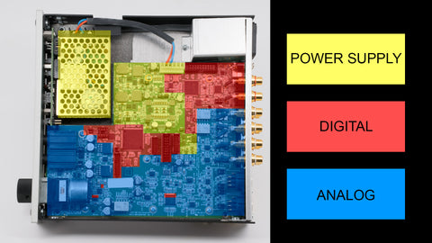
DAC2 Internal View
Switching Power Supplies
Benchmark has transitioned to switching power supplies because they have the potential to be much quieter than conventional linear power supplies (see Audio Myth "Switching Power Supplies are Noisy" for a more detailed discussion of this topic).
Conventional power supplies have large magnetic components that operate at the AC line frequency (50 - 60 Hz). Magnetic emissions from these components are the primary source of the AC hum that can be heard in the noise floor of most audio products. In contrast, the DAC2 has a natural "white" noise floor without any audible traces of AC hum. To achieve a white noise floor, the AC line-related tones must be at least 20 dB to 30 dB lower than the noise measured across the entire audio band. The DAC2 has an A-Weighted SNR of 126 dB, while AC line-related hum is below -160 dB, relative to full output. This means that the AC line-related hum is at least 34 dB lower than the idle-channel noise of the DAC2 (easily achieving a virtually perfect white noise floor). This can be seen in the following FFT plot taken from the DAC2 manual:
DAC2 Idle Channel Noise Spectrum

A similar plot for the DAC1 (from the DAC1 manual) shows that AC line-related hum measures -128 dB, relative to full output:
DAC1 Idle Channel Noise Spectrum

This comparison shows that AC line-related hum was reduced by more than 30 dB by using switching power supplies in the DAC2! This is why we say that it is a myth that linear supplies are quieter than switching supplies.
Video Demonstration - Seeing is Believing!
Two months ago, we released an application note featuring a video demonstrating the magnetic immunity of star-quad microphone cables. We exposed the cables to the stray magnetic fields produced by a variety of power supplies, including some rather noisy low-cost switching supplies. We also exposed the cables to the fields produced by a DAC1 and a DAC2. The DAC1 produced magnetic interference, but the DAC2 did not. The difference? The DAC2 has a switching power supply that is optimized for audio application while the DAC1 has a traditional linear power supply. The video shows that the switching power supply in the DAC2 is much quieter than the linear power supply in the DAC1. The comparison is not even close! Sometimes seeing is believing!
Watch a short clip from this video and help put an end to another audio myth!
Switching Power Supplies Must be Optimized for Audio
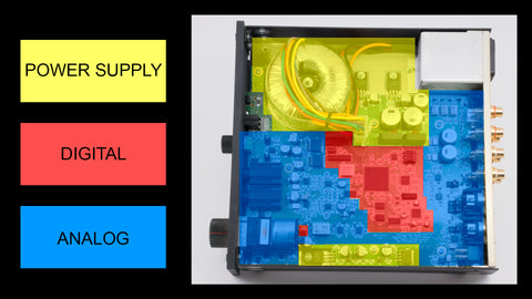
It is important to understand that switching supplies must be specially designed to be quiet within the audio band. To do this, Benchmark operates the magnetic components at frequencies ranging from 200 kHz to 1 MHz. This keeps the power supply noise well above audio frequencies where it can easily be removed with analog filters, if necessary. More importantly, the power supply interference is much lower when the magnetic components are operating at high frequencies. For a given power requirement, transformer size decreases as the switching frequency increases. The magnetic components in the DAC2 are very small. The magnetic fields emitted by these components are much smaller than the magnetic fields emitted by the large toroidal transformer in the prior generation DAC1 converter. The following photo shows the large transformer used in the DAC1:
DAC1 Internal View
Power Supply Noise in Audio Systems
Power supplies can add noise to the audio through one or more of these paths:
- Conducted Interference
- Electrostatic Interference
- Magnetic Interference
Conducted Interference
Conducted interference is caused by noise voltages that are conducted through the power supply connections. Power supply output filters and bypass capacitors (capacitors between the power supplies and ground) can help to mitigate conducted interference.
Electrostatic Interference
Electrostatic interference occurs when a noise voltage is capacitively coupled from one conductor to another. A power supply conductor may capacitively couple to adjacent audio conductors. This type of radiated interference is easily mitigated with the use of ground planes and shielded conductors. Shielding becomes more difficult as the interference frequency increases. Switching supplies can emit more electrostatic emissions than linear supplies, but with the proper choice of switching frequencies, this noise can be entirely above the audio band. If the interference is above the audio band, it can be removed with filters that will have no impact on the audio.
Magnetic Interference
In an audio product, magnetic interference is often the most problematic because it is difficult to mitigate. Magnetic fields radiated by a transformer can directly induce currents in sensitive sections of an analog audio circuit. If this interference is line-frequency interference (from a linear supply), it will fall within the audio band where it cannot be easily separated from the audio. On the other hand, if this interference comes from a high-frequency switching power supply, it will lie above the audio band where it can be filtered out without impacting the audio. Electrostatic shielding will not block magnetic interference.
Immunity
Audio circuits can be designed for immunity to conducted, electrostatic, and magnetic interference.
Immunity to Conducted Interference
Audio circuits can be designed to reject conducted noise voltages on the power supply rails. Power supply rejection ratio (PSRR) is a measure of a circuit's ability to reject noise voltages on the power supply rails. The audio circuits in the DAC1 and DAC2 converters are designed to have a PSRR of more than 100 dB at AC line frequencies. We can test the PSRR by applying a noise signal to a power supply rail while measuring the noise at the output of the audio circuit being driven from the noisy rail. For example, if we apply a 1 volt 60 Hz sine wave to the +18V or -18V analog supply rails in a DAC1 or DAC2, this will produce a voltage that is less than -100 dB volts (0.00001 volts) at the analog outputs. This is a PSRR of 100 dB at 60 Hz.
Immunity to Electrostatic Interference
Audio circuits can be shielded to reject electrostatic coupling of noise voltages. Benchmark products use 6-layer printed circuit boards (PCBs) with a unique inside-out construction. The outer two layers are connected to ground and provide a shield above and below the signal traces that are carried almost entirely by the four internal layers. For this reason, there are almost no signal traces visible from the top or bottom of Benchmark circuit boards. Unused space on the internal layers is also filled with a ground plane. Sensitive traces are surrounded on all sides by ground plane or grounded guard traces. The outer edges of our circuit boards have vertical connections (vias) between the ground layers that form an electrostatic picket fence around the perimeter of the circuit board. Many additional via connections tie all sections of the various ground planes into a single integrated shield. This shield is highly effective at blocking electrostatic interference from the power supply and other external sources. This shield also prevents the emission of noise from digital circuits. For this reason, Benchmark products will often pass EMI emissions tests with the chassis cover removed.
Immunity to Magnetic Interference
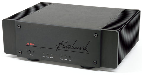
It is important to note that electrostatic shielding does not block magnetic interference. Magnetic immunity requires the use of expensive magnetic shielding materials and/or the use of symmetrical geometric and electrical structures that cancel the effects of magnetic coupling. Star-quad cables have a symmetrical geometry that causes a precise matching of the magnetic interference on the + and - legs of the audio interconnect. When these legs feed a balanced input, most of the magnetic interference is removed. Benchmark has extended this technique to interconnects that are internal to the printed circuit board. In our microphone preamplifiers we connect the XLR inputs to the preamplifier circuit using star-quad traces using two of the internal circuit board layers. We use the same technique in reverse, inside the AHB2 power amplifier. High-current circuits and their high-current ground returns run through a quadrupole structure of four traces. This symmetrical structure cancels the magnetic fields that would otherwise be emitted by the high-current traces. The XLR input signals on the AHB2 run through a similar quadrupole structure on their way to a precision balanced input amplifier. The AHB2 also includes two magnetic shielding plates that are fabricated from a material that is designed to attenuate magnetic fields. The magnetic components in the DAC2 and AHB2 are encapsulated in ferrite housings that help to minimise radiated magnetic fields.
Regulation
Audio circuits do not place a constant load on a power supply. The loading changes with every musical peak and it is not unusual to have some audio conducted through the power supply rails. If bypass capacitors are placed near each audio buffer, the higher audio frequencies can be shunted to ground in order to reduce the audio signal on the power supply rails. The lowest audio frequencies must be removed by the regulators within the power supply. Voltage regulators attempt to maintain a constant voltage while the load is changing.
The DAC2 has a distributed regulator system. There are 20 separate voltage regulators within the DAC2. Each is dedicated to one specific subsystem. This segregation minimizes crosstalk between subsystems and eliminates the need to deliver regulated voltages over long distances. Voltages are regulated at the point of load.
The ES9018 D/A converter chip has two voltage reference inputs that have a PSRR of 0 dB (no rejection). These left and right reference inputs are very sensitive to noise. Any noise on these inputs will also appear on the output pins of the ES9018. To mitigate this potential problem, we use a precision voltage reference, a multistage passive filter and a high-bandwidth low-noise buffer to regulate each of these reference inputs. This custom regulator is not the low-cost cookbook solution that you will find in most other products that feature the ES9018. This Benchmark regulator is one key to the low noise and low distortion delivered by the DAC2 converter.
Summary
The strategy within the DAC2 is fourfold:
- Minimize sources of interference
- Keep the interference above the audio band
- Maximize immunity to interference
- Provide separate regulators for each subsystem
Switching supplies operating above 200 kHz minimize the power supply noise and keep it out of the audio band. The analog circuits are designed to reject noise on the power supply rails, and the rails include bypass capacitors at every point of load. The printed circuit board uses a special inside-out construction that provides a complete Faraday cage for the audio circuits. Each critical subsystem has its own voltage regulators. These regulators separate analog, digital, and clock loads to prevent interactions. The left and right voltage reference inputs on the ES9018 are the most critical points in the system. These inputs are equipped with a regulator that Benchmark created specifically for this task.
Never judge a D/A converter by the choice of a D/A conversion chip. The power supply, the analog processing, the digital processing, and the circuit board layout all contribute to the overall performance of the D/A.
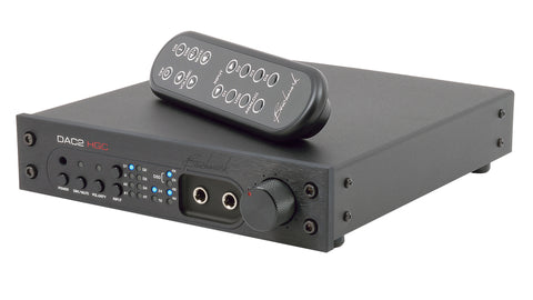
Benchmark DAC2 HGC D/A Converter
Benchmark AHB2 Power Amplifier