Digital Processing in Audio D/A Converters
The Benchmark DAC2 is an audio digital-to-analog converter. This application note explains the proprietary digital processing inside Benchmark's DAC2 D/A converter.
Analog Processing - "90% of the Magic"
In part 1 of this series we made the case that 90% of the components in an audio converter are analog, and that about 90% of the "magic" happens in the analog processing.
DAC2 Digital Processing - "10% of the Magic"
The 10% of a D/A converter that is digital cannot be taken for granted. The digital section often makes a significant contribution to the sound of an audio D/A converter. This is especially true when the digital processing is complemented by a very pure and clean analog section. With a highly transparent analog section, some of the subtleties of the digital processing can become apparent.
ES9018 D/A Conversion Chip
The DAC2 uses the finest D/A conversion chip available. It is the ES9018 "Sabre" D/A made by ESS Technology. This chip can deliver the lowest THD and lowest noise of any currently available D/A chip. The full potential of this chip can only be realized when it is surrounded by the very best analog processing.
The ES9018 is a very flexible D/A converter and there are many processing options available to the designer. For this reason, and the reasons stated in "Part 1 - Analog Processing" it is unlikely that any two different products with the ES9018 will sound or measure exactly the same.

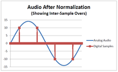
Benchmark reserves the top 3.5 dB of the ES9018 for headroom to prevent clipping of intersample peaks. These peaks can occur many times per second and they cause clipping and overloads in digital processing systems that lack digital headroom. Digital systems need at least 3.01 dB of headroom above 0 dBFS to prevent this problem. The DAC2 may be the only ES9018-based D/A converter that solves this problem. This important issue is covered in detail near the end of this application note. In this diagram "10" and "-10" represent the maximum positive and negative digital codes. Note that the peaks of the analog waveform can be substantially higher than these maximum codes. To fully understand why this headroom is required, it is helpful to look at the entire digital processing chain.
Channel Summing Reduces Noise
The ES9018 is actually an 8-channel 32-bit converter. Benchmark sums two groups of 4 channels together in order to deliver the two channels required for the DAC2. This summing reduces the random thermal noise produced by the individual channels of the ES9018. Random noise is reduced by up to 3 dB every time the number of summed channels doubles. The 4:1 summing delivers a 6 dB improvement over the single-channel performance of the ES9018. Benchmark's low-noise regulator and low-noise I-V converters allow us to extract even more performance from the ES9018 (see Part 1 and Part 3 of this series of application notes).
Fully-Balanced Conversion
If we look inside the ES9018 we will see that each 32-bit channel is actually a balanced pair of 32-bit converters. As a balanced pair they deliver very low THD. But if either side was used by itself, THD would be much higher. For this reason it is very important to follow the ES9018 (or any modern D/A converter IC) with a differential amplifier. As we pointed out in "Part 1", the common-mode THD components produced by the D/A will cancel in a well-trimmed differential amplifier. The degree to which these common-mode distortion components cancel is a function of the precision of the differential amplifier. Benchmark uses very high precision trimmed components to achieve outstanding common-mode rejection. In contrast, many competing products omit the differential amplifier entirely.
6-bit Sigma Delta Modulators
As we dig deeper into the ES9018, we see that each 32-bit half of each channel is actually an oversampled sigma-delta 6-bit converter using a high oversampling ratio. The oversampling ratio is left to the discretion of the designer. Benchmark ran a number of tests to determine the sweet spot for the oversampling ratio in the ES9018. We chose the oversampling ratio that delivered the lowest THD. PCM is delivered to the D/A elements in a format that closely resembles DSD-Wide.
Massive Array of 1-bit Converters
If we step further into the ES9018, we see that each of the 6-bit converters are actually an array of 64 equally-weighted 1 bit converters. Using an array of 1-bit converters eliminates the linearity errors that always occur when using binary weighted elements.
The maximum 6-bit code is represented by turning all 64 of the 1-bit elements on. The minimum 6-bit code is represented by turning all 64 elements off. The half-scale (code 32) is represented by turning 32 elements on.
While it is easier to match the sizes of 1-bit elements than it is to match a more -conventional binary-weighted ladder array, it is still impossible to match 64 individual elements with enough precision to deliver 20 to 24-bit accuracy. 21-bit accuracy would require a matching of 1 part in 2,097,152 (0.00005%). The ES9018 solves this problem by randomly selecting which of the 64 1-bit converters will get turned on. This random mapping changes on every clock cycle and this eliminates the linearity errors that would have been caused by slight mismatches in the size of the 1-bit elements. The matching errors create a small amount of noise above 1.7 MHz instead of producing in-band distortion products. The 1.7 MHz out-of-band noise is easily removed by the analog low-pass filters in the DAC2 output stage. The result is an output signal with extremely low THD+N.
The net result is that the 6-bit converters have the near-perfect linearity of a 1-bit converter while achieving an 18 dB reduction in noise (due to the 64:1 parallel structure). This improvement delivers a 6-bit sigma-delta modulator that has an 18 dB noise advantage over a classic 1-bit sigma-delta converter (such as that used in DSD).
The array of 1-bit converters also allows native DSD conversion with digital volume control. This combination of features is very unusual, but the ES9018 provides a unique solution to the DSD volume control problem. Normally, it is very difficult to implement a digital volume control (or any other form of digital processing) in a 1-bit DSD system, but with an array of 1-bit converters, we can set the volume by controlling how many DSD converters are turned on.
512 1-bit Converters Per Channel
Time for a little math: Each channel of the DAC2 uses 4 fully-differential converters. Each half of one differential converter has 64 1-bit converters. This means that each output on the DAC2 is derived from 64*2*4=512 1-bit converters operating at megahertz sampling rates. These 512 1-bit converters are the equivalent of a 9-bit converter with perfect linearity. The DAC2 essentially has a 9-bit sigma-delta converter for each channel. The sigma-delta modulation is running at a very high oversampling ratio and is driven by 32-bit data. In the DAC2 this brute-force redundancy is followed by precision analog processing. Together these digital and analog elements give the DAC2 its industry-leading THD and noise performance.
Digital Filter Options in the ES9018
There are a number of filter options in the ES9018. Many of the options allow an undesirable fold-back of ultrasonic images (a form of aliasing). The designer can choose from this palette of filters or the designer can load the ES9018 with custom filter coefficients. Some designers tend to focus on time domain response without realizing the damage that this can do in the frequency domain. Digital filters can be designed to artificially shorten transients but when this is done, the transient position is modulated by the relative phase between the transient and the samples. Furthermore, these specialized time-domain optimizations allow fold-back of ultrasonic images of the base-band audio. This image fold-back is a form of aliasing.
The ES9018 even allows operation without any low-pass filter. This completely defeats almost all of the advantages of sigma-delta conversion. When the ES9018 is incorrectly configured, or "optimized for time domain response", it can produce audio with severe quantization noise and image fold-back issues. I have seen one ESS-based converter that had a "no filter" option available to the user. This dreadfully bad option defeats the sinx/x reconstruction filter and this produces digital stair steps at the analog outputs. The designers claimed they "liked the way it sounded".
Frequency Shifting the Transition Band
Benchmark has selected the ES9018 filters which provide the lowest pass-band ripple. We then frequency-shift the filter transition band upward so that it is centered at 110.5 kHz. We do this by operating the ES9018 at an input sample rate of 211 kHz. This means that the entire transition band of the ES9018 filter is always above the highest audio frequency contained in the incoming audio. At a 192 kHz incoming sample rate, the highest incoming frequency is 96 kHz. This is completely below the lower limit of the transition band that is centered at 110.5 kHz. Benchmark's system effectively eliminates the filters in the ES9018 by frequency shifting the filters out of the audio band. It also completely eliminates all traces of image fold-back. The Nyquist frequency of the D/A converter exceeds the Nyquist frequency of the incoming digital audio.
We used this same frequency-shifting technique in our DAC1 converters. When the DAC1 was designed, the available technology limited us to a D/A input sample rate of 110 kHz. In the DAC1, the D/A filters were out of band for sample rates up to 96 kHz. The DAC2 extends this unique technology to all sample rates up to 192 kHz. The goal for all Benchmark converters has always been to make the digital filters as transparent as possible. The accuracy and precision of the filters is a function of the oversampling ratio used in the filters. Benchmark moves the low-pass filter out of the D/A converter so that it can be executed at a much higher oversampling ratio.
Conceptual Oversampling
The digital filters in the DAC2 operate at a conceptual sample rate of about 250 GHz. Incoming audio is conceptually upsampled to 250 GHz and then down sampled to 211 kHz using a filter that mathematically behaves as if it is operating at a 250 Giga-sample-per-second rate. We use the word "conceptual" because the calculations and internal clocks are not actually running at 250 GHz. Due to the mathematics of upsampling, most of the filter calculations require a multiply by zero operation. These unnecessary zero-product calculations are eliminated while all of the non-zero calculations are executed. The net result is mathematically equal to the results that would have been produced by executing every calculation at a 250 GHz sample rate. Eliminating the unnecessary calculations reduces the DSP and processing rates to a manageable load.
4-picosecond Timing Accuracy
The 250 GHz conceptual sample rate gives us the ability to time-shift the audio waveform in 4-picosecond steps without altering the wave shape. This time interval is very short: Light travels about 1 foot in 1 nanosecond. In 4 picoseconds, light only travels 4/1000 of a foot. Sound travels much slower (about 1 foot in 1 millisecond), and can only move 0.00000005 inches in 4 picoseconds.
If we can detect jitter on the incoming audio, our 250 GHz system can correct jitter-induced timing errors to within 4 picoseconds using nothing more than a conceptual 250 GHz shift register. But, to make this work, something has to control the timing correction circuit. The shift register and a control circuit form the Benchmark UltraLock2™ jitter attenuation system.
UltraLock2™ - Asynchronous Jitter Removal
If we want to remove jitter it may seem logical to try and measure the jitter-induced timing errors on a sample-by-sample basis. Unfortunately this technique would have errors exceeding 1000 picoseconds and would produce very poor results. A much better technique is to measure the frequency ratio between the incoming jittery clock and a stable clock that is used for D/A conversion. Over a sufficiently long period of time we can calculate the frequency ratio of the two clocks to a very high precision. The incoming samples can be buffered and then shifted out at a rate that is determined by this precision ratio. If the ratio is locked down and not allowed to change, all of the jitter will be removed, but if frequency of the incoming clock drifts, we may eventually run out of space to store incoming samples, or run out of samples in our buffer. On the other hand if we allow the ratio to track any slow drift in the incoming sample rate, we can manage our data buffering requirements, but some low-frequency jitter will be encoded into the audio waveform as it passes through to the output clock domain. The key is to only allow very slow changes in the ratio calculation. To do this, the DAC2 has a ratio tracking filter with a corner frequency set to about 1 Hz. All interface jitter above 1 Hz is rejected, while interface jitter below 1 Hz is encoded into the output waveform. The 1 Hz corner frequency was selected because jitter frequencies below 1 Hz are far too low to cause audible problems. The magnitude of interface jitter below 1 Hz is also very small.
Waveform Delivery using UltraLock2™
The 250 GHz conceptual shift register inside the UltraLock2™ system allows delivery of the audio waveform to the D/A converter with a timing error of less than 4 picoseconds. The clock ratio measuring system calculates the ratio between the incoming sample rate and the fixed-frequency 27 MHz clock that is used to generate the 211 kHz input sample rate to the ES9018 D/A chip. This system keeps all jitter-induced distortion at levels that are at least 140 dB below the music. This level is so low that the jitter-induced distortion would be inaudible if it was played by itself. Any digital audio signal that can be decoded by the DAC2 will be reproduced without audible or measurable traces of jitter-induced distortion. This means that the optical, coaxial, and USB interfaces on the DAC2 deliver identical jitter performance. Furthermore, the jitter performance of the DAC2 is not a function of cable length or cable type.
Headroom for Intersample Peaks
Digital PCM signals have clipping thresholds that are very precisely defined by the largest positive and negative codes. Digital meters show 0 dBFS whenever either of these two codes are reached. This is an indication that clipping may have occurred. If the peak of a sine wave just reaches the largest positive and negative codes, its level is 0 dBFS. But, if the peaks don't happen to occur at the exact sampling instant (and they usually don't), digital meters will read a lower level. If the peaks of the sine wave are precisely positioned between the samples, the sine wave can reach a level of +3.01 dBFS before the digital meters will show a clipping event. For this reason, many of the peaks in commercial CD recordings exceed 0 dBFS. These intersample peaks often occur many times per second and they can become even more frequent when a CD is subjected to MP3 compression. In most D/A converters, an intersample over will produce a burst of high-frequency noise. The DAC2 will not produce these bursts of digital noise.

Intersample peaks can go undetected by digital meters, but they can cause clipping whenever the digital audio is upsampled. Upsampling will correctly reproduce the intersample peaks unless the digital processing clips or overloads. This clipping of intersample peaks is a common occurrence in most oversampled sigma-delta D/A converters. DSD avoids this problem by eliminating the upsampling operation, but DSD brings a number of performance problems of its own. The solution is not DSD. The solution is to build oversampled PCM D/A converters that will not clip intersample peaks.
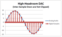
How Much Headroom?
The entire digital processing chain in the DAC2 has 3.5 dB of headroom above 0 dBFS. Intersample peaks cannot cause clipping in any digital section of the DAC2. Furthermore, all of the analog stages that follow have 5 dB of headroom above 0 dBFS. This means that the DAC2 will correctly reproduce all intersample peaks without any clipping, compression or distortion. The DAC2 is one of very few D/A converters that can make this claim. We believe this is the single most important innovation in the DAC2, and we believe it is one of the largest contributors to the overall sound quality of the DAC2. The ability to reproduce intersample peaks trumps all other digital processing enhancements.
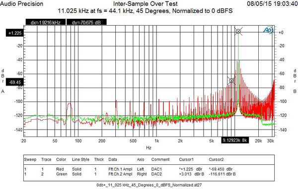
Measurements Suggest that Inter-Sample Clipping is Audible
The following spectral plot shows an 11.025 kHz tone at a level of +3.01 dBFS being played through a Benchmark DAC1 (red curve) and a DAC2 (green curve). The additional digital headroom in the DAC2 prevents the numerous intermodulation distortion products that can be seen in the red curve. Note that these distortion products are very high in amplitude and they should therefore be clearly audible. When playing music, intersample peaks will cause busts of similar intermodulation products. Our experience in the listening room has confirmed the audibility of DSP overloads due to inter-sample peaks. Most converters clip whenever an inter-sample over occurs. The DAC2 will not clip these overs. This is probably the single most important improvement in D/A technology in the the past 10 years! This difference explains 90 to 100 % of the audible differences between the DAC1 and the DAC2. It also sets the DAC2 apart from almost all other D/A converters.
32-bit Digital Volume Control
The DAC2 has a 32-bit digital volume control that feeds the array of 32-bit D/A converters. This 32-bit connection allows the use of digital volume control without causing a loss of resolution. At an attenuation of 48 dB, all bits from a 24-bit input still reach the D/A converter. When the DAC2 is properly gain-matched to a power amplifier, the noise produced by the DAC2 will remain inaudible at all volume control settings. The XLR outputs on the DAC2 are equipped with passive analog attenuators which should be used to optimize the gain range of the volume control. This hybrid volume control system is another key to the overall performance of the DAC2. It allows optimization of the output level to match the input sensitivity of any power amplifier.
Dual-Mode Asynchronous USB System
The USB audio input on the DAC2 can operate in two different modes. USB Audio 1.1 supports sample rates up to 96 kHz and it is supported by almost all operating systems including those used in portable devices. The USB input can be switched to a USB Audio 2.0 mode that supports high sample rates and DSD. This mode will run on most Apple devices without a driver, but current versions of Windows still require a driver. In the near future, Windows operating systems may add native support for USB Audio 2.0.
The audio standard, USB Audio 2.0, should not be confused with the generic USB 2.0 standards. USB Audio 2.0 is transported at USB 2.0 data rates using USB 2.0 or 3.0 ports. The existence of a USB 2.0 or 3.0 port does not imply that the operating system will natively support the USB Audio 2.0 format.
The DAC2 USB interface uses the asynchronous data transfer mode to pull audio data from the computer. A clock generated inside the DAC2 is used to transfer the data. The asynchronous mode eliminates the need to recover a conversion clock from a potentially noisy computer-generated clock. For this reason, the asynchronous transfer mode produces almost no jitter, and any jitter that is produced by the USB subsystem is fully-removed by the UltraLock2 jitter attenuation system.
Automatic Digital De-Emphasis
Some of the very earliest CD recordings used a pre-emphasis system to overcome the limitations of early D/A converters. These early D/A converters were equipped with analog de-emphasis filters that were automatically switched on when the pre-emphasis flag bit was detected. Some modern D/A converters omit the de-emphasis function and this means that theses converters will play some of these early CDs with an incorrect frequency response.
The DAC2 has automatic de-emphasis, but this function has been moved to the digital domain where it can be executed with much higher precision. Because of the vast improvements in D/A conversion performance, it no longer makes sense to apply de-emphasis in the analog domain. Modern D/A converters that support de-emphasis, do so in the digital domain. You may never play a recording that uses pre-emphasis, but if you do, the DAC2 will automatically apply a very precise de-emphasis curve.
Conclusion
The ES9018 is a very flexible D/A converter chip. It offers simple solutions that require very few external components, but it also offers opportunities to extract much higher performance. Benchmark has elected to perform most of the digital processing outside of the ES9018. Most importantly, Benchmark has extended the digital headroom to a level that is 3.5 dB higher than the headroom available inside the ES9018. The result is that the DAC2 will never clip when it encounters an intersample over. These overs occur many times per second in most CDs.
There are wide variations in the measured performance of products that use the ES9018 converter chip. Never assume that the sound of a converter is determined by the D/A chip alone!
More Application Notes in This Series
"Inside the DAC2 - Part 1 - Analog Processing" discusses the analog processing found in the DAC2.
"Inside the DAC2 - Part 3 - Power Supplies" discusses the power supplies in the DAC2.


